
Mould equipment for pipeline section coating and methods for coating of pipeline sections with moulds

a technology of moulding equipment and pipeline sections, which is applied in the field of moulding equipment for pipeline sections and methods for coating pipeline sections with moulds, can solve the problems of time-consuming and costly casting and/or machining of special shapes of pipeline sections molds from steel, and achieves the effects of less cost, flexible design and quick production

Active Publication Date: 2018-09-11
PIPELINE INDUCTION HEAT
View PDF13 Cites 0 Cited by
  • Summary
  • Abstract
  • Description
  • Claims
  • Application Information

AI Technical Summary

Benefits of technology

The invention is a mold for coating pipeline sections with molten coating material from an injection molding machine. The mold is made of a shell of impervious material reinforced by an exoskeleton of non-distensible material. This design is lighter, quicker and less expensive compared to a mold made from solid steel and can be easily adapted to different shapes of coating. The mold components can also be recycled for use in other molds. The technical effect is an improved and flexible solution for coating pipeline sections with a cost-effective and versatile mold.

Problems solved by technology

Casting and / or machining a special shape of pipeline section mold from steel is costly and time consuming.

Method used


Image

  • Mould equipment for pipeline section coating and methods for coating of pipeline sections with moulds
  • Mould equipment for pipeline section coating and methods for coating of pipeline sections with moulds
  • Mould equipment for pipeline section coating and methods for coating of pipeline sections with moulds

Examples


Embodiment Construction

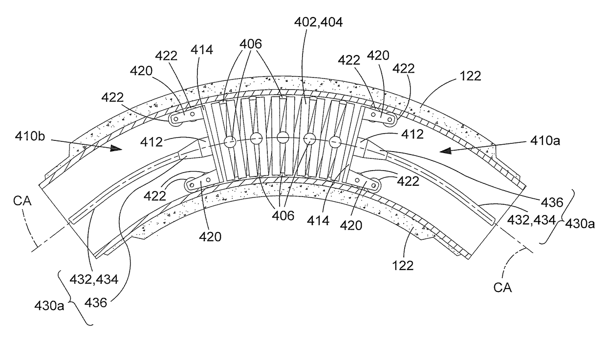
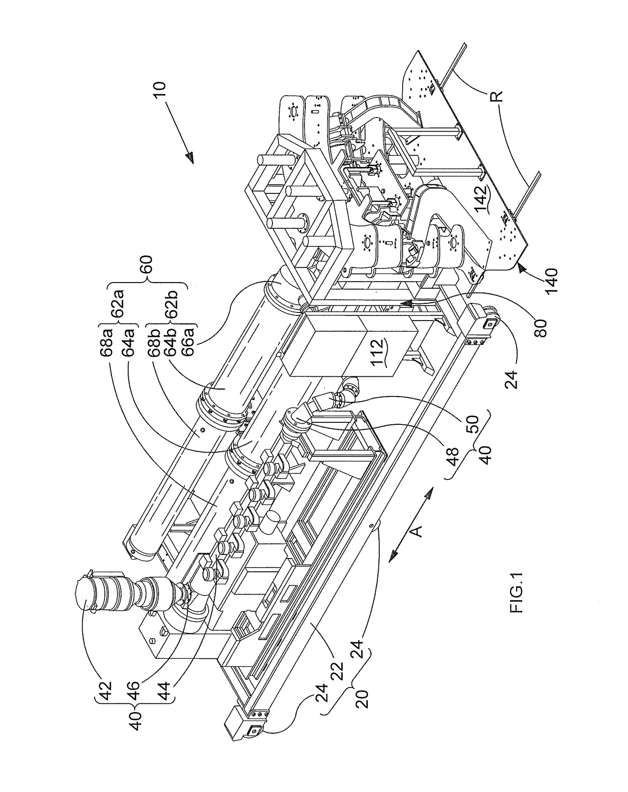
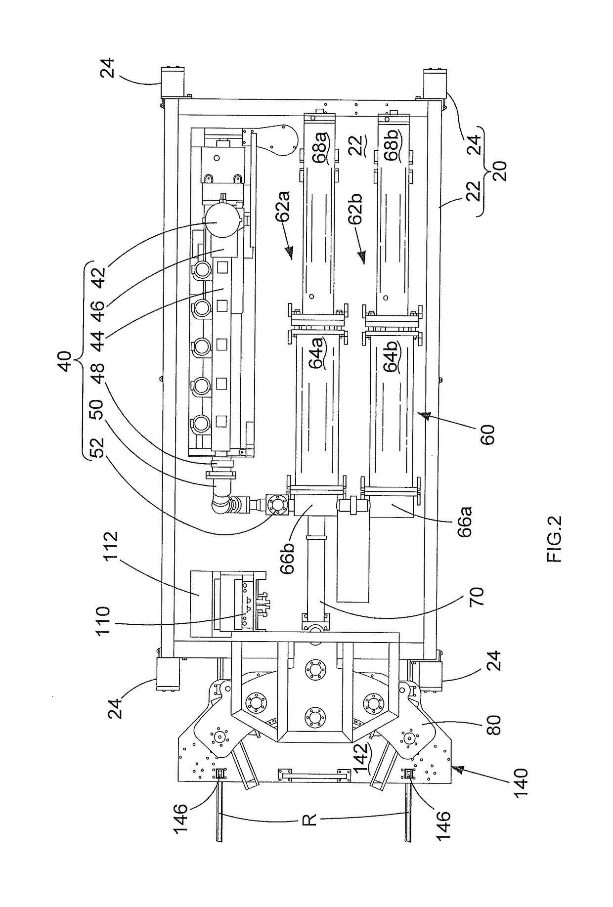
[0087]Referring to FIGS. 1 to 5, an IMPP injection molding machine 10 for factory-applied coating of steel pipeline sections comprises a main support frame 20 onto which are mounted an extruder assembly 40, an accumulator assembly 60, a mold support frame assembly 80, and a hydraulic control circuit 110. Typically, these components are connected together by nuts and bolts so that the IMPP machine 10 may be disassembled and packed into a container for transportation from factory to factory. When reassembled for use in a factory, the control circuit 110 is connected to a hydraulic power supply from a generator or a shore supply. The main support frame 20, the extruder assembly 40, the accumulator assembly 60, the mold support frame assembly 80, and the control circuit 100 each have lifting pints (not shown) to facilitate disassembly and reassembly of the IMPP injection molding machine 10 with the help of an overhead crane.

[0088]The main frame assembly 20 comprises a generally rectangu...


PUM

PropertyMeasurementUnit
thicknessaaaaaaaaaa
forceaaaaaaaaaa
arc sweep anglesaaaaaaaaaa

Abstract

A mold for coating a pipeline section with molten coating material from an injection molding machine, wherein the mold Includes a shell of impervious material reinforced by an exoskeleton of non-distensible material. An assembly for supporting a mold including a plurality of mutually separable shell bodies for coating a pipeline section, wherein the assembly includes motorized opening and closing of the shell bodies in a straight line. An assembly for supporting a bent pipeline section wherein the assembly includes a base and a pair of arms extending from the base, wherein each arm includes a respective clamping collar for clamping a bent pipe section between the arms. A vehicle for induction heating a bent pipeline section, wherein the vehicle includes a helical induction coil; and wheels arranged to guide movement of both ends of the induction coil through a tubular inside face of a bent pipeline section.

Description

CROSS-REFERENCE TO RELATED APPLICATIONS[0001]This application claims priority, under 35 U.S.C. § 119(a)-(d), to UK Patent Application No. GB 1314340.9 filed Aug. 9, 2013, the contents of which are incorporated herein by reference in its entirety.FIELD OF THE INVENTION[0002]The present invention relates to improvements in mold equipment for pipeline section coating, improvements in methods for making mold equipment and improvements in methods for coating of pipeline sections with molds.BACKGROUND OF THE INVENTION[0003]Pipelines in the oil and gas industry are typically formed from multiple lengths of steel pipeline sections that are welded together end-to-end as they are being laid. To prevent corrosion of the pipeline sections and to reduce heat loss of fluids transported by pipelines, the pipeline sections are coated with one or more protective or insulative layers. The pipeline sections are usually coated at a factory remote from the location in which they are to be laid. This is ...

Claims


Application Information

Patent Timeline
Patent Type & Authority Patents(United States)
IPC IPC(8): H05B6/38H05B6/10B29C45/14B29C45/17B29C33/30F16L59/22F16L55/162F16L58/18F16L59/20F16L58/10B29D23/00B29K509/08B29L23/00
CPCB29C45/14598B29C33/307B29C45/1744B29D23/00F16L55/162F16L58/109F16L58/181F16L59/20F16L59/22H05B6/101H05B6/38B29C33/302B29L2023/004B29C2791/003B29D23/001B29K2509/08B29L2023/001B29C33/00B29C45/14B29C45/1459F16L58/00F16L58/10F16L58/1054F16L53/35F16L53/00F16L55/26
Inventor GEORGE, MICHAELDIBBLE, ANTHONYBARKER, NICHOLAS
Owner PIPELINE INDUCTION HEAT
Learn More