Switched capacitor circuit modifying voltage on the inductor of a buck regulator

a voltage regulator and buck technology, applied in the field of voltage regulator devices, can solve the problems of high efficiency voltage regulators that cannot be integrated on the chip, charge sharing losses, and the efficiency degradation of deviating from the target operation point, so as to reduce reduce the voltage drop on the inductor. , the effect of reducing the size of capacitors

Active Publication Date: 2018-09-04
AMERICAN UNIVERSITY IN CAIRO
View PDF10 Cites 5 Cited by
  • Summary
  • Abstract
  • Description
  • Claims
  • Application Information

AI Technical Summary

Benefits of technology

[0005]In one aspect, embodiments of the invention include a voltage regulator having a switched capacitor circuit (SCC) capable of switching its output voltage periodically between two or more voltage levels, thus providing a smaller voltage drop on the inductor. The voltage regulator devices include a switched capacitor circuit (e.g., using flying capacitors) that takes an input voltage and is capable of providing different voltage levels. The switched capacitor circuit is followed by a low pass filter to give a regulated output voltage. The switched capacitor circuit is configured to switch its output periodically between several different voltage levels (e.g., adjacent levels) allowing for smaller inductor sizes and smaller capacitor sizes without degrading the performance. The device can be used for DC-DC power conversion both on-chip and off-chip, and used to provide a regulated DC output voltage to power electronic circuits. In one embodiment, the invention is capable of providing three types of voltage conversion that include step-up, step down and step-up / down conversions.
[0006]In a further aspect, embodiments of the invention include methods for operating voltage regulators using a phase interleaving technique where a complete switching cycle is divided into a predetermined number of time slots, e.g., double the maximum number of phases, providing any voltage level of the SCC. Each time slot is assigned one of the phases of two or more different conversion ratios. Given a certain desired output voltage range, some phase sequences lead to a reduced number of switching MOSFETs during a complete switching cycle which in turn reduce switching losses. In addition, some phase sequences lead to lower stress on switching capacitors allowing for smaller capacitor sizes and less charge sharing losses. Preferable conditions and constraints for proper operation of the circuit under this method are also provided. Interleaving the phases of different voltage levels increases the effective switching frequency of the circuit and reduces switching losses.
[0009]Advantageously, embodiments of the invention fills the gap between inductor-based voltage regulators and capacitor-based voltage regulators. While each type of these voltage regulators has its advantages and disadvantages, the voltage regulator according to embodiments of the current invention takes the advantages of both regulator types, while avoiding or minimizing their disadvantages. The voltage regulator according to one embodiment is a general structure where many specific voltage regulators targeting different applications can be built based on the principles of the general structure. In one aspect, the voltage regulator is assigned with a controlling technique that helps in a further boost of its performance that can be considered as an optimum solution for challenges and requirements of modern voltage regulators.
[0010]Advantageously, embodiments of the voltage regulator have small passive components, making it an integrable on-chip device that consumes less area off-chip. These aspects enable electronic devices with smaller size. For modern processors, the trend is to increase the number of cores on the chip, where each core needs a separate voltage regulator to support the dynamic voltage and frequency-scaling feature. Embodiments of the current invention provide a regulator that is integrable on chip and with high efficiency.

Problems solved by technology

Integration of high efficiency voltage regulators on chip is a challenge.
While normal switched capacitor voltage regulators (SCVRs) are easy integrable, they are suffering from charge sharing losses as well as fast degradation of efficiency when deviating from the target operation point.
On the other hand, conventional buck converters suffer from large magnetic components that introduce challenges to integrate on chip.

Method used


Image

  • Switched capacitor circuit modifying voltage on the inductor of a buck regulator
  • Switched capacitor circuit modifying voltage on the inductor of a buck regulator
  • Switched capacitor circuit modifying voltage on the inductor of a buck regulator

Examples


Embodiment Construction

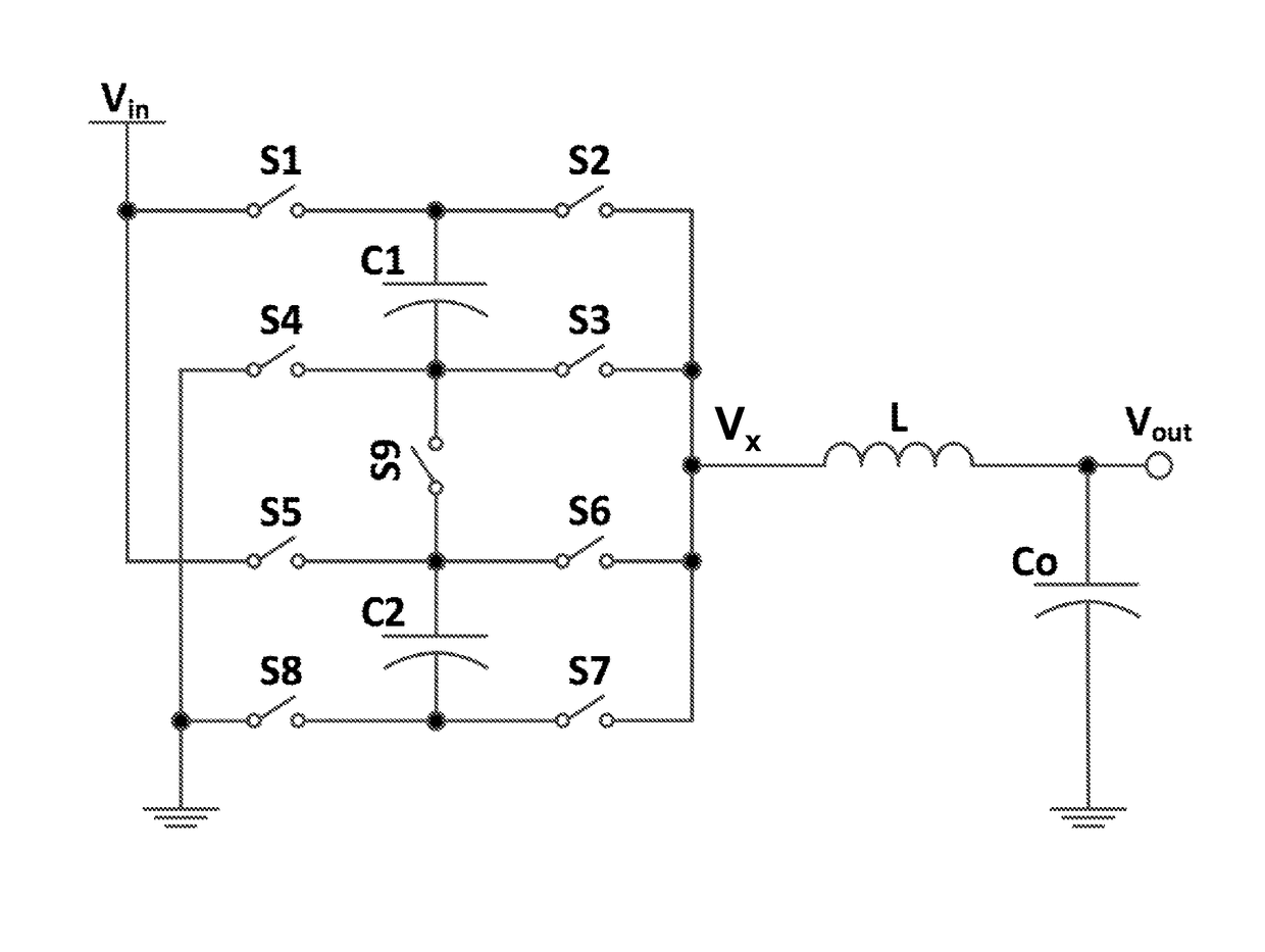
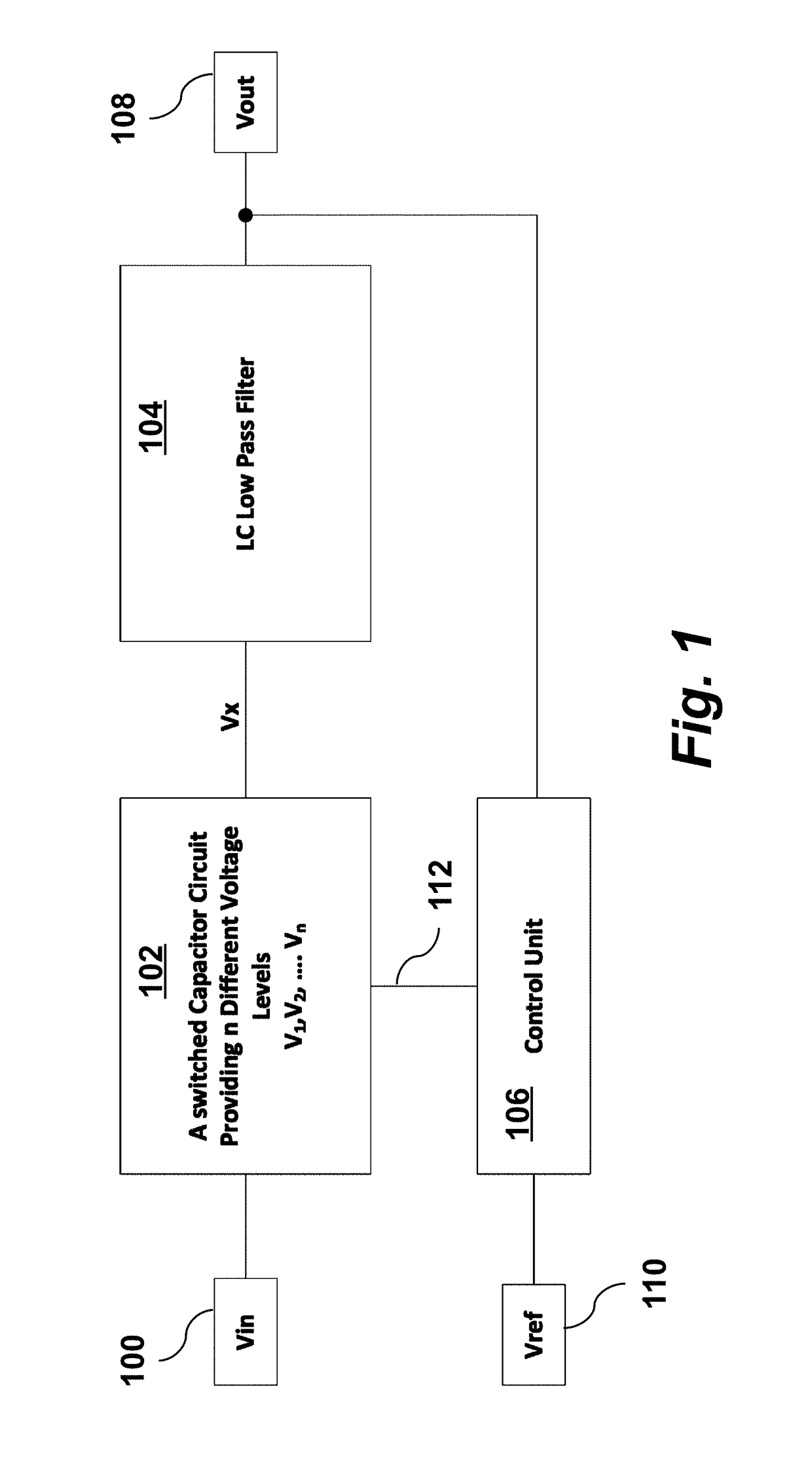
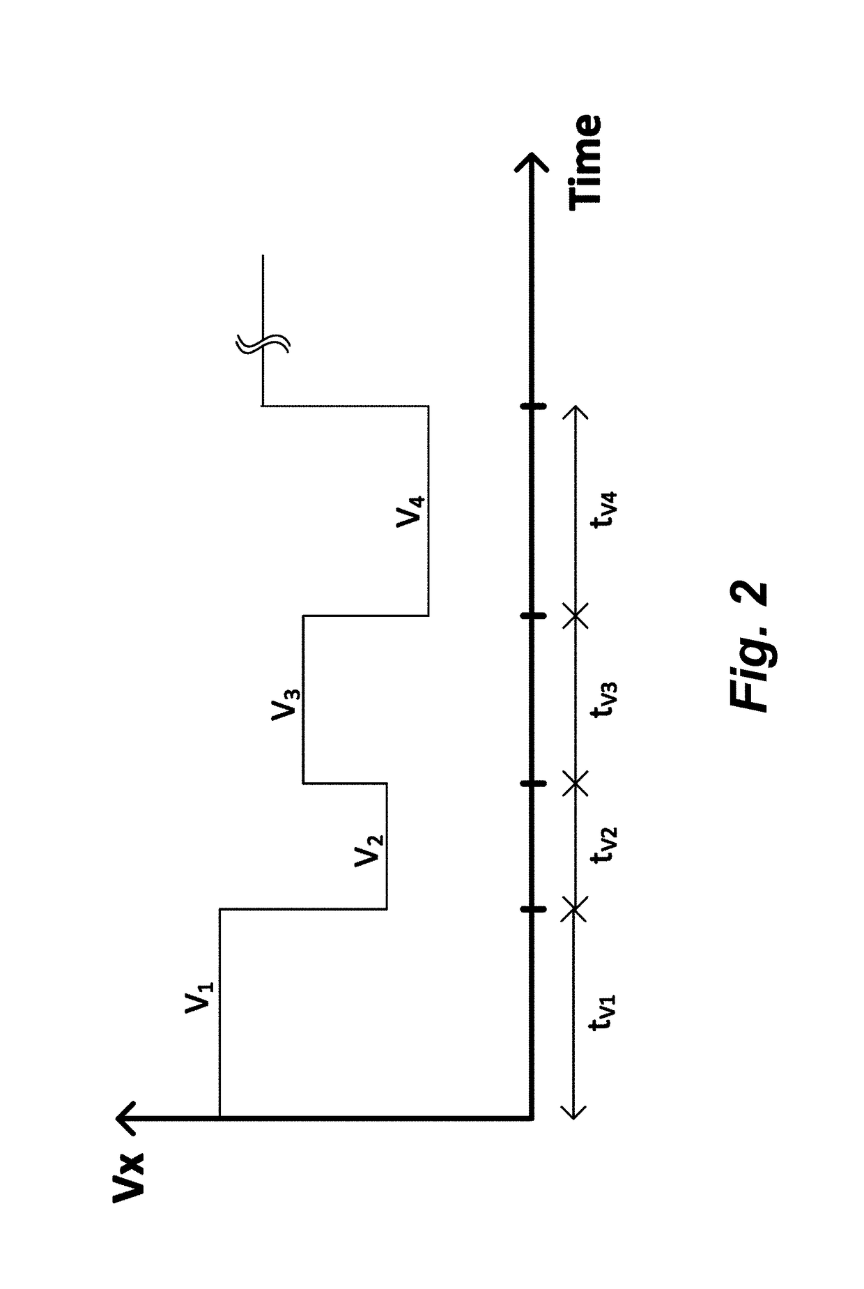
[0033]A multilevel multistate voltage regulator design according to principles of the present invention is described in detail below with references to FIGS. 1-3. This design uses a switched capacitor circuit (SCC) to switch between different levels in different phase and the use of an inductor and the use of a duty cycle control with switch cap to get arbitrary output voltage. In the general case, the SCC switches its output between any number of voltage levels periodically. In one example, the SCC is switching its output periodically between two voltage levels. A method for operating DC-DC converters by phase interleaving technique is also described below in relation to FIGS. 4-5. This method for interleaving phases and clocks reduces power consumption. In general, the phases of any number of voltage levels may be interleaved. In one example, the phases of two voltage levels are interleaved. A method to operate DC-DC converters by resistance modulation of switches using a duty cyc...


PUM


Abstract

A voltage regulator provides a regulated output voltage [108] from an input voltage [100] using control unit [106] to control a switched capacitor circuit [102] to periodically produce different output voltage levels Vx followed by a low pass filter [104] to give a regulated output voltage. Phase interleaving is used where the phases of different voltage levels are interleaved allowing for increased effective switching frequency and reduced switching losses. By controlling the average voltage on the flying capacitors, output voltage is regulated by modulating the resistance of the switches using a duty cycle. A control unit [106] is used to determine the operation region of the voltage regulator device and configure the switched capacitor circuit in each operation region. The controller contains a state machine that determines the switches configuration in each phase of a complete switching cycle.

Description

CROSS-REFERENCE TO RELATED APPLICATIONS[0001]This application is a 371 of PCT / US2015 / 015696 filed on Feb. 12, 2015. PCT / US2015 / 015696 filed on Feb. 12, 2015 claims the benefit of U.S. Provisional Application 61 / 940,337 filed on Feb. 14, 2014FIELD OF THE INVENTION[0002]The present invention relates generally to voltage regulator devices (also known as DC-DC converters) and methods for operating them. More particularly, the invention relates to DC-DC converters capable of providing step-up, step-down or step-up / down conversions.BACKGROUND OF THE INVENTION[0003]Modern microprocessors have many cores integrated on one chip. Each core is preferred to operate at a different supply voltage domain to support the dynamic voltage and frequency scaling feature. This means each core requires a separate voltage regulator that has high efficiency over a wide range of output voltage levels. Integration of high efficiency voltage regulators on chip is a challenge.[0004]While normal switched capacit...

Claims


Application Information

Patent Timeline
Patent Type & Authority Patents(United States)
IPC IPC(8): H02M3/07H02M1/08H02M1/00
CPCH02M3/07H02M2001/0003H02M1/08H02M1/0003H02M1/0095H02M3/155
Inventor ABDULSLAM, ABDALLAH AMGADISMAIL, YEHEA
Owner AMERICAN UNIVERSITY IN CAIRO
Why Eureka
Try Eureka