
Input device

a technology of input device and input circuit, which is applied in the direction of electric controllers, instruments, ignition automatic control, etc., can solve the problems of increasing cost, wasting power, and wasting power, and achieve the effect of not wasting power

Inactive Publication Date: 2005-09-22
ONKYO KK
View PDF3 Cites 5 Cited by
  • Summary
  • Abstract
  • Description
  • Claims
  • Application Information

AI Technical Summary

Benefits of technology

[0007] It is therefore an object of the present invention to provide an input device capable of determining which key switch is turned ON based on the value of the voltage input to the key input terminal of the microcomputer, wherein the microcomputer is operable in a power saving mode without having to provide a comparator and without wasting power by intermittently operating the microcomputer.
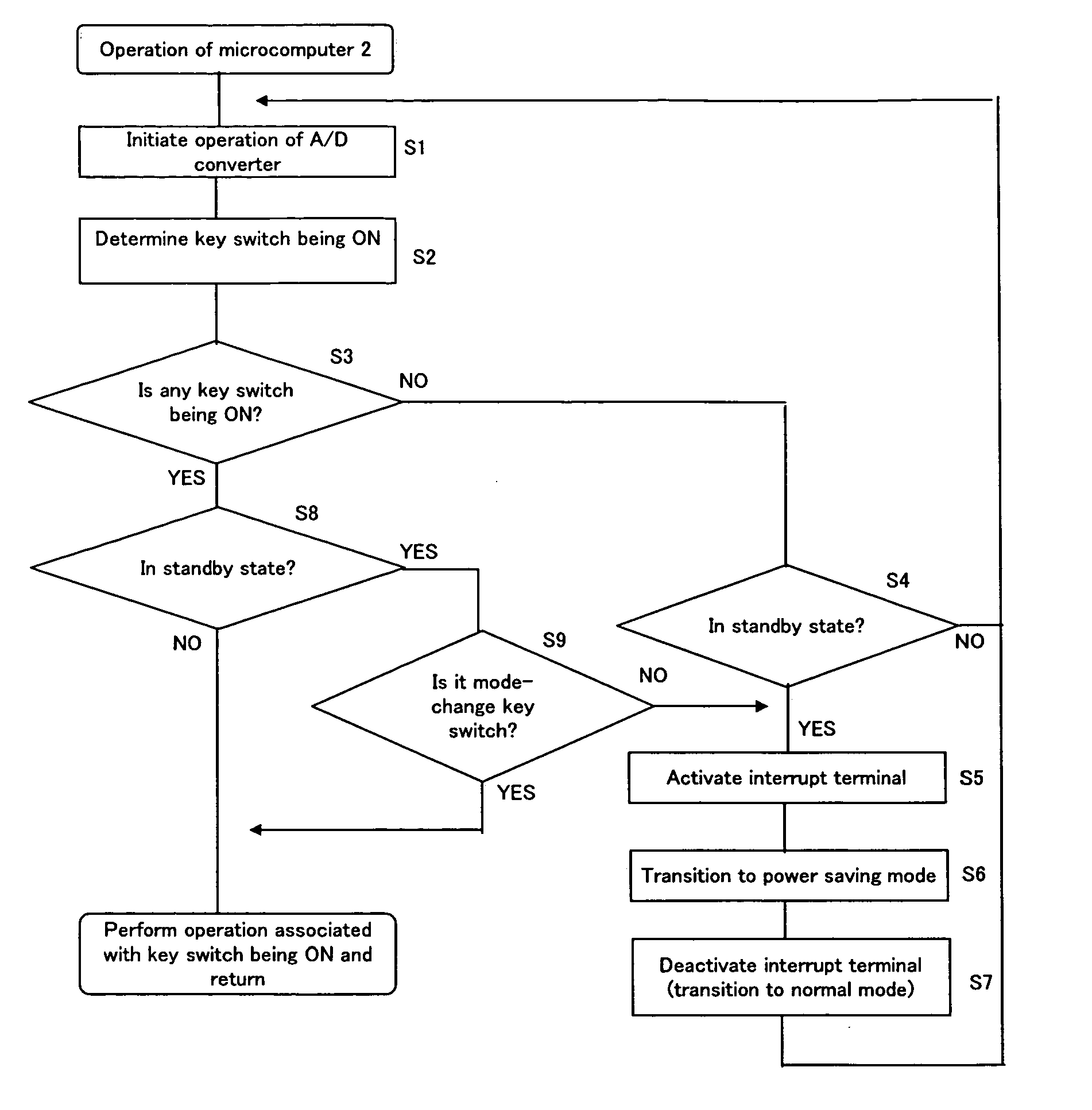
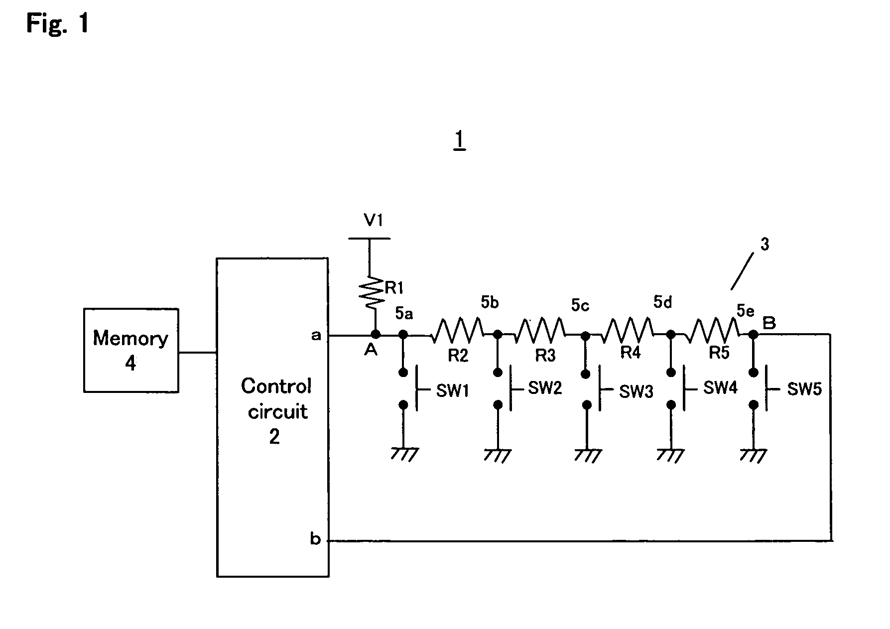
[0013] The connection node between the resistor and the key switch of the first voltage determination circuit is at the external power supply voltage when the key switches are all OFF, and when a key switch is turned ON, the connection node is at a voltage value associated with the key switch. The connection node between the resistor and the key switch of each of the voltage determination circuits other than the first voltage determination circuit is at the external power supply voltage (high level) when the key switches are all OFF, and is at a low-level voltage when a key switch is ON. Therefore, when a key switch is turned ON, the control circuit can transition from the power saving mode to the normal mode.
[0017] By setting the impedance of the interrupt terminal to be higher than the combined impedance of the input circuit, the voltage drop through the resistors of the input circuit can be made very small. Since the voltage drop through the resistors can be made small, when no key switch is being ON, a predetermined voltage can be applied to the key input terminal without a decrease in the predetermined voltage. Therefore, it is possible to prevent the control circuit from erroneously detecting a key switch activation when no key switch is being ON. Moreover, since the voltage drop through the resistors can be made small, it is possible to reduce the amount of power to be consumed through the resistors.
[0019] Therefore, if a non-mode-change key switch is turned ON while the control circuit is in the power saving mode, the control circuit once transitions to the normal mode but immediately transitions back to the power saving mode. Therefore, it is possible to further reduce the standby power consumption.

Problems solved by technology

However, Japanese Patent Laid-Open No. 9-198169 requires the provision of an OR circuit and a general-purpose input terminal for each key switch, thereby complicating the circuit configuration.
However, the scanning signal is a cause of noise, and such a configuration is inappropriate particularly in AV applications.
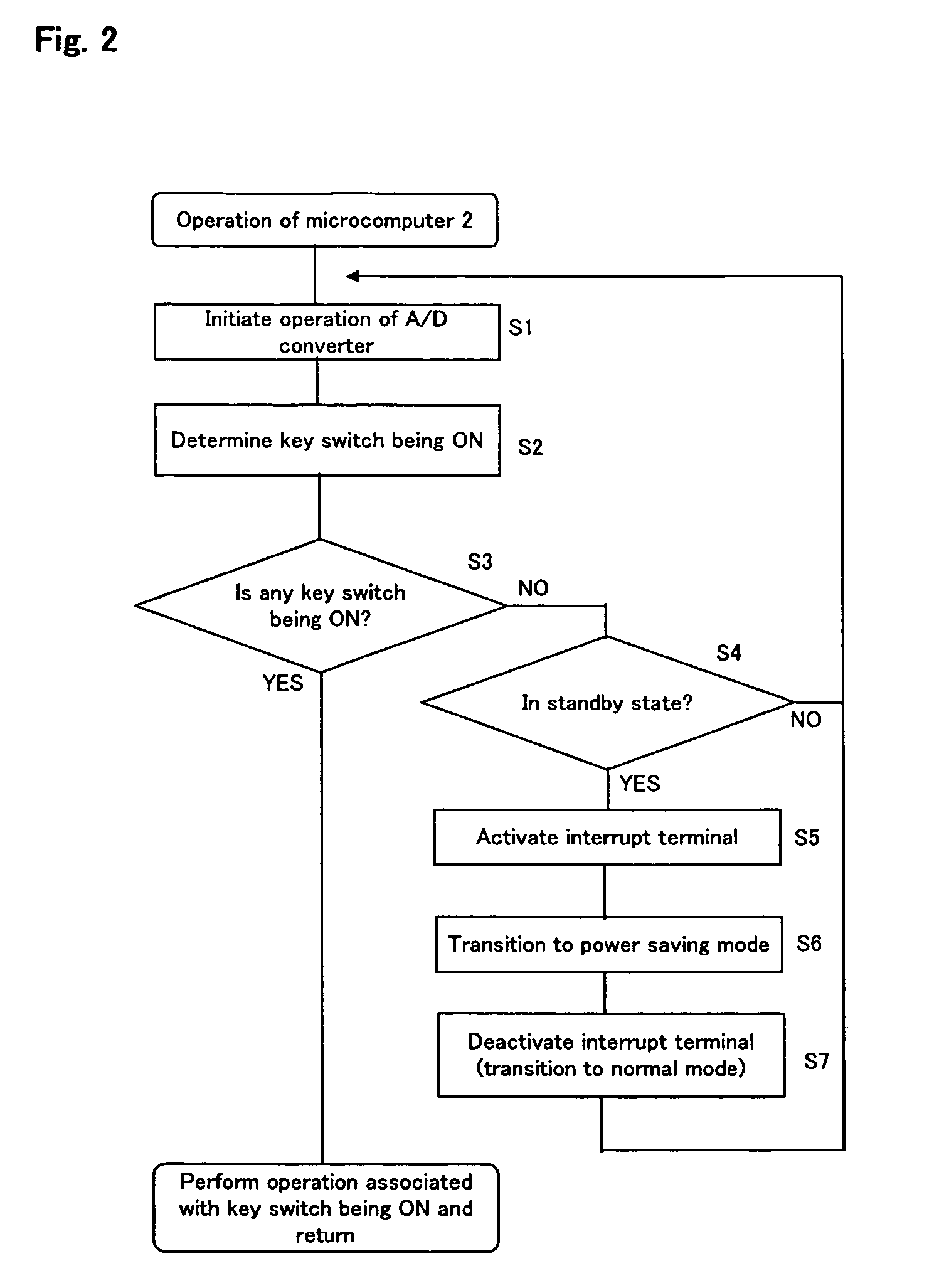
When a key switch is turned ON, the comparator 505 applies an interrupt signal (a low-level voltage) to an interrupt terminal b. With the circuit 501, however, it is necessary to provide a comparator so as to be able to exit the power saving mode, thus increasing the cost.
However, since the microcomputer is operated intermittently in a standby state, the standby power consumption cannot be reduced sufficiently.

Method used


Image

  • Input device
  • Input device
  • Input device

Examples


Embodiment Construction

[0029] Preferred embodiments of the present invention will now be described with reference to the drawings. The present invention is not limited to these embodiments. FIG. 1 is a schematic circuit diagram showing an input device 1 according to a preferred embodiment of the present invention. The input device 1 is a circuit for A / D-converting the voltage input to the microcomputer to determine which key switch is turned ON, and includes a control circuit 2 and an input circuit 3. A device to which the input device 1 is applicable is operable in a standby state in which power is supplied only to the microcomputer and the peripheral circuits thereof so that the power of the device can be turned back ON in response to a user's operation of a key.

[0030] The control circuit 2 controls the operation of an electronic device (e.g., a CD player) to which the input device 1 of the present embodiment is applicable, and is typically a microcomputer. The microcomputer 2 is connected to a memory ...


PUM


Abstract

An input device includes an input circuit including a plurality of key switches connected in parallel to one another, and a control circuit including a key input terminal to which a first terminal of the input circuit is connected, and an interrupt terminal to which a second terminal of the input circuit is connected. When a key switch is turned ON, an interrupt signal is input from the second terminal of the input circuit to the interrupt terminal, whereby the control circuit transitions from a power saving mode to a normal mode. Then, the control circuit determines which one of the key switches is turned ON based on a value of a voltage applied from the first terminal of the input circuit to the key input terminal. Thus, it is possible to realize a power saving mode without having to provide a comparator.

Description

BACKGROUND OF THE INVENTION [0001] 1. Field of the Invention [0002] The present invention relates to an input device, and more particularly to an input device operable in a power saving mode in which a microcomputer is shut down in a standby state. [0003] 2. Description of the Related Art [0004] An electronic device such as an AV device has an operation state, called a “standby state”, where power is supplied only to the microcomputer and to the peripheral circuits thereof so that the power of the device can be turned back ON in response to a user's operation of a key or a remote control even when the power of the device is OFF. Recently, there is a demand for further reducing the standby power consumption, i.e., the amount of power to be consumed in a standby state. In view of such a demand, the microcomputer has a power saving mode in which the microcomputer itself is shut down when the microcomputer has no process to execute. Then, in response to a user's operation of a key, an i...

Claims


Application Information

Patent Timeline
IPC IPC(8): G06F1/26G06F1/32G06F3/02
CPCG06F1/3215
Inventor ITO, KAZUNARI
Owner ONKYO KK
Learn More