
Luminous textile

a technology of luminous textiles and lampshades, applied in the field of luminous lamps, can solve the problems of dim light, eye soreness of familiar objects,

Inactive Publication Date: 2008-07-31
TUAN WEI JEI
View PDF3 Cites 7 Cited by
  • Summary
  • Abstract
  • Description
  • Claims
  • Application Information

AI Technical Summary

Benefits of technology

[0006]Accordingly, the present invention is to provide a luminous textile with interesting and glittering effect to meet people's needs, also with pressure sensitive mechanism to emit light without wasting power for unexpected light emissions.

Problems solved by technology

However, artificial selection means anything familiar to us is gradually come to eye sore.
Besides, most of such LEDs are electrified by swaying spring, which may be swayed insufficiently and out of contact with LEDs to cause dim light.

Method used


Image

  • Luminous textile
  • Luminous textile
  • Luminous textile

Examples


Embodiment Construction

[0018]The present invention is described in detail according to the appended drawings hereinafter.

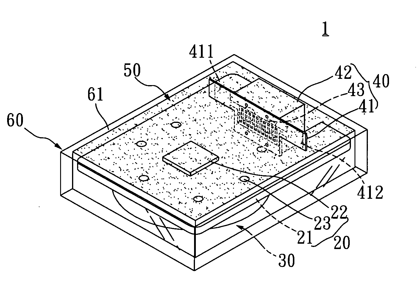
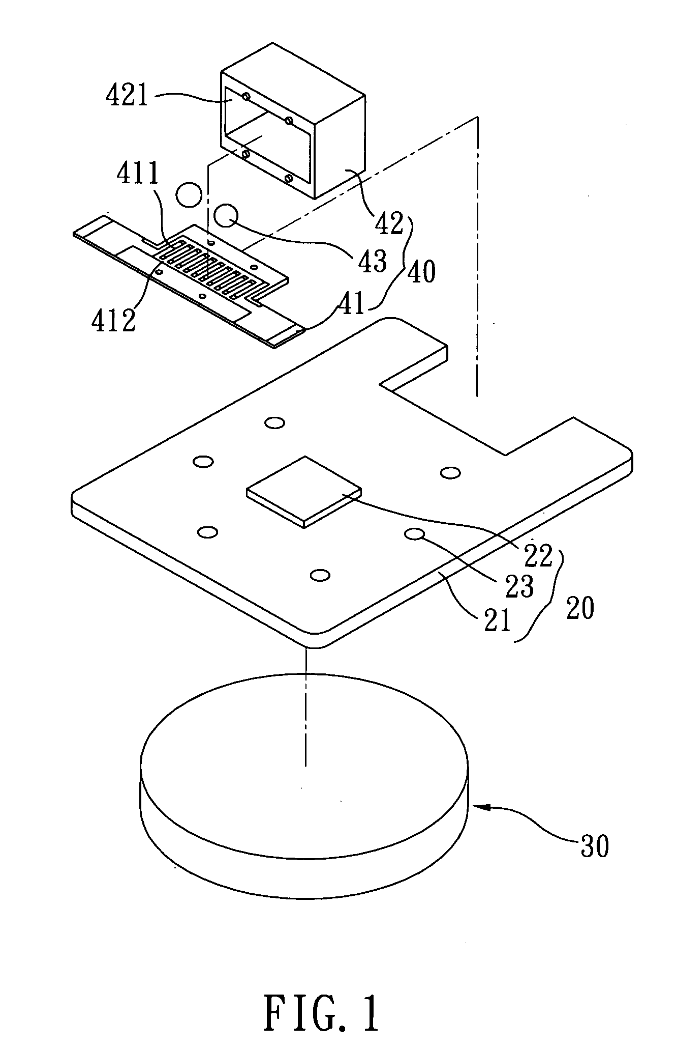
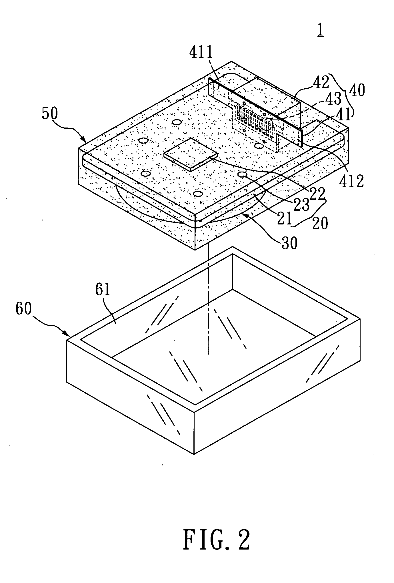
[0019]As shown in FIG. 1˜FIG. 3, the luminous lamp (1) includes a light emission electric circuit (20), at least, a battery (30); a pressure sensitive switch (40), a plastics (50) and an insulated housing (60).

[0020]Said light emission electric circuit (20) includes a first printed circuit board (PCB) (21), a control integrated circuit (IC) (22), and a plurality of light emission diodes (LEDs) (23). Said first PCB is approximately square in shape, a first surface on the first PCB is configured with an electric circuit. (not shown) While the control IC (22) is disposed to the first surface of the first PCB further electrically connected to the electric circuit on the first PCB. Each of the LEDs (23) is installed on the first surface of the first PCB (21) and electrically connected to the electric circuit of the first PCB (21). In the drawings, six LEDs (23) installed on the PCB (21) is e...


PUM


Abstract

The present invention is related to a luminous textile comprising a luminous lamp coupled to a pad, which is further coupled to the textile. The luminous lamp includes a light emission electric circuit, a battery, a pressure sensitive switch, and a plastics. The light emission electric circuit includes a first printed circuit board (PCB), a control integrated circuit (IC), and a plurality of light emitting diodes (LEDs); the light emission electric circuit is electrically connected to the battery as a power supply to conduct electricity, the pressure sensitive switch is electrically connected to the first PCB, said light emission electric circuit, battery and pressure sensitive switch is enclosed by the plastics pervious to light. When the pressure sensitive switch is vibrated, each of LEDs activated to emit light one by one in sequence.

Description

[0001]The present invention is continuation in part of U.S. application Ser. No. 11 / 657,627 filed on Jan. 25, 2007.FIELD OF THE INVENTION[0002]The invention is to provide a luminous lamp; particularly applied to a textile activated by vibrations to emit light.BACKGROUND OF THE INVENTION[0003]Nowadays, material standard of living is already defined as a “well clad and well fed” life style. When wearing, not only keeps warmth about a wearer's body, but also amuses one's companions. Therefore, either put on clothing or shoes, wearers are likely moved by ideas such as update your styles—and get tied to the cause, value added accessory showing off together with peers is sought.[0004]In accompaniment with advanced technology, a lot of electronics are applicable to luminous objects. On the market, integrated circuit (IC) coupled with light emitting diodes (LEDs) is already applied to shoes, packs etc. Especially when wearers walk on the side walk with shoes emitting light to please the eye...

Claims


Application Information

Patent Timeline
Patent Type & Authority Applications(United States)
IPC IPC(8): F21V21/00F21V9/16
CPCA41D27/085H01H35/02G09F13/22G09F9/33
Inventor TUAN, WEI-JEI
Owner TUAN WEI JEI
Learn More