Circuit configuration and method for limiting current intensity and/or edge slope of electrical signals

a technology of electrical signals and circuit configuration, which is applied in the direction of electronic switching, pulse manipulation, pulse technique, etc., can solve the problems of long time, cost-encumbered and risk-encumbered reworking of a switching assembly, and achieve low space requirements, easy parameterization, and cost-effective implementation.

Inactive Publication Date: 2013-07-25
ROBERT BOSCH GMBH
View PDF13 Cites 5 Cited by
  • Summary
  • Abstract
  • Description
  • Claims
  • Application Information

AI Technical Summary

Benefits of technology

The present invention provides a circuit configuration that can limit both current and edge, which can be cost-effectively and easily adapted to different applications. This can be done by using a few standard components, without needing to modify the driver circuit. The circuit configuration can also be used as a driver stage, or as a pre-driver to control the output of another circuit. Additionally, the circuit configuration can provide a targeted effect on signal edge dropping and minimize voltage drop in the switched-on state of the switching element.

Problems solved by technology

Consequently, a lengthy, cost-encumbered and risk-encumbered reworking of a switching assembly may be omitted.

Method used


Image

  • Circuit configuration and method for limiting current intensity and/or edge slope of electrical signals
  • Circuit configuration and method for limiting current intensity and/or edge slope of electrical signals
  • Circuit configuration and method for limiting current intensity and/or edge slope of electrical signals

Examples


Embodiment Construction

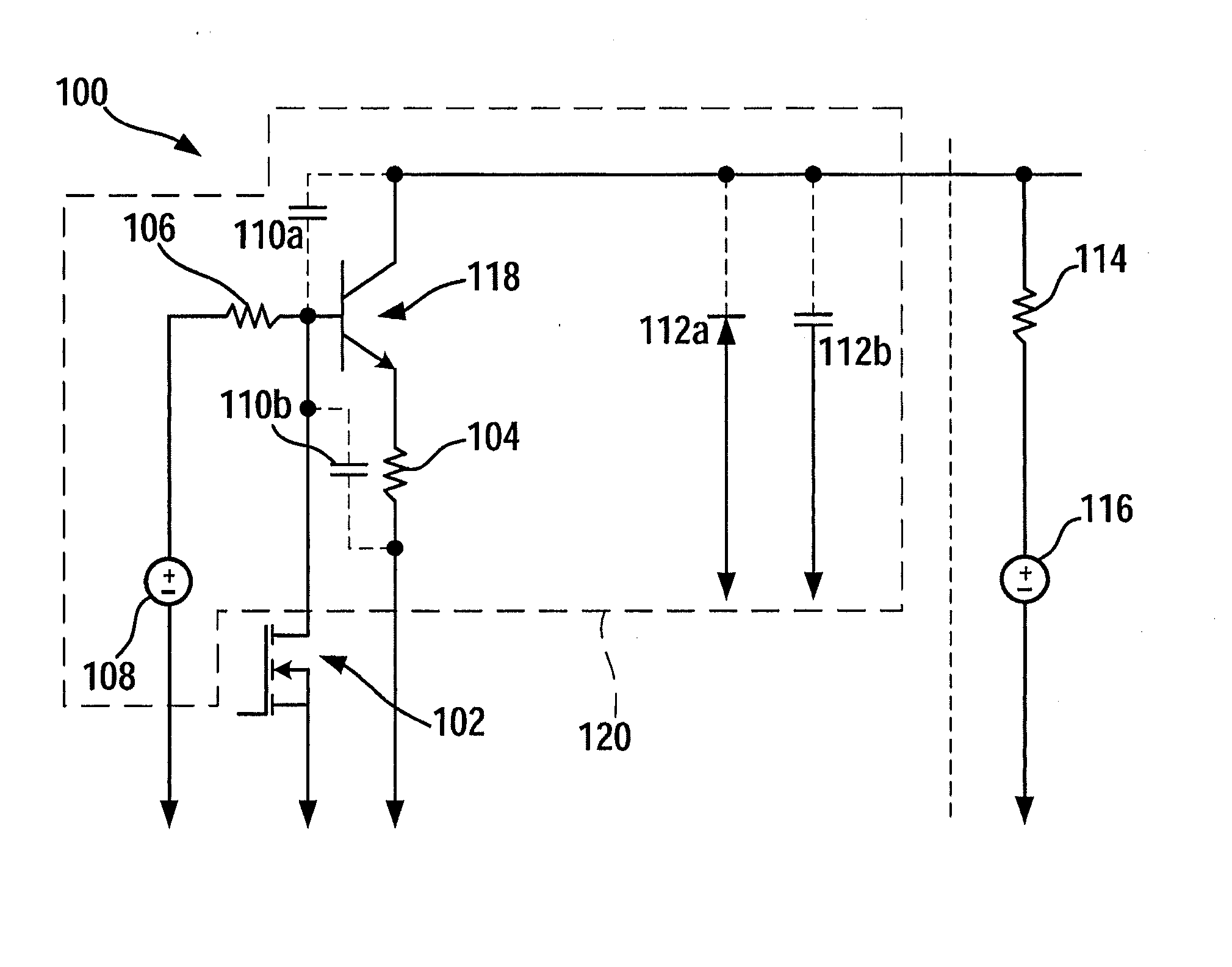
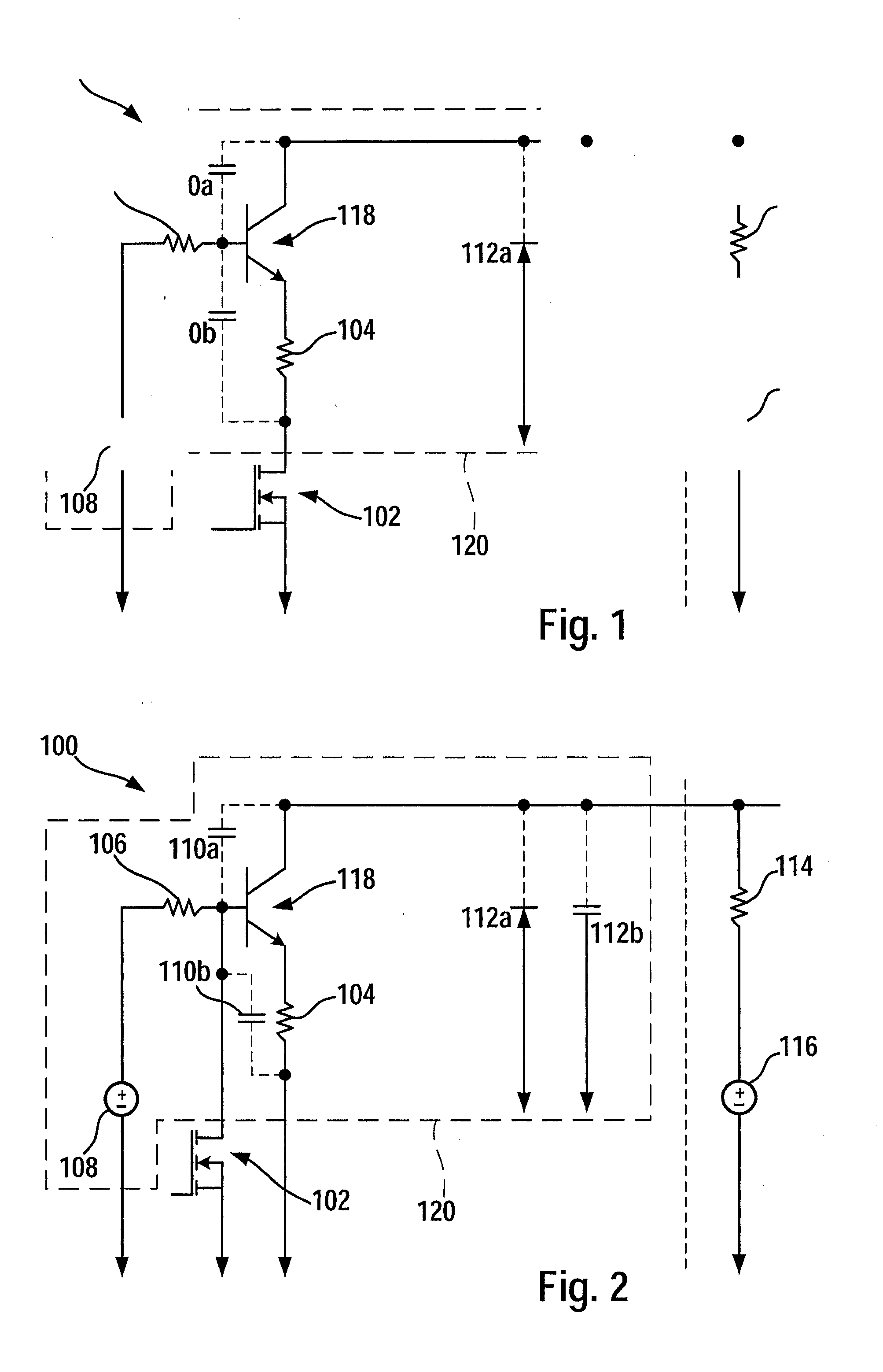
[0022]FIG. 1 shows a first exemplary specific embodiment of a circuit configuration for limiting current intensity and / or the edge slope of electrical signals, according to the present invention.

[0023]Circuit configuration 100, in this instance, is made, as an example, of an npn transistor 118, whose base is connected to a fixed potential 108. The connection may take place, for instance, via resistor 106 or via a voltage divider. The emitter of element 118 is connected to switching element 102 via a component 104 having a resistor. Switching element 102 is that element which, viewed overall with element 114 having a resistor and voltage source 116, is to be broadened by the current limitation and / or the edge slope limitation while using limitation unit 120.

[0024]Optionally, at the base of limiting element 118 of limiting unit 120 circuit configuration 100 may have provided to it a capacitive element 110a,b. In this instance, capacitive element 110a may be connected between the base ...


PUM


Abstract

A circuit configuration for the limiting of current intensity and / or the edge slope of electrical signals includes: a voltage source; a switching element connected to the voltage source and equipped for switching the voltage source; and a limiting unit functionally positioned between the switching element and the voltage source, the limiting unit being equipped to limit a current intensity and / or an edge slope of an electrical signal in response to a switching process of the voltage source while using the switching element.

Description

BACKGROUND OF THE INVENTION[0001]1. Field of the Invention[0002]The present invention relates to a circuit configuration and a method for limiting the current intensity and / or the edge slope of electrical signals.[0003]2. Description of the Related Art[0004]Electrical switching elements, such as drive components, usually have a fixed, unchangeable edge slope, which may not be adapted to a desired application case in optimum fashion. For example, when standard components are used or standard assemblies, it may not always be possible to influence an internal drive current of the respective standard element. Even a specified short circuit limitation, to the extent that a switching element used has one, may not always be adapted optimally to a special, desired application case.[0005]Too high an edge slope of a switching process or clock-pulsed signals may, among other things, exceed EMC emission boundary values (electromagnetic compatibility) and thus injure it.[0006]Furthermore, too hi...

Claims


Application Information

Patent Timeline
Patent Type & Authority Applications(United States)
IPC IPC(8): H03K5/04
CPCH03K17/0828H03K5/04H03K17/166
Inventor KOEHLER, INGO
Owner ROBERT BOSCH GMBH
Why Eureka
Try Eureka