Connection method in addition to a functional part which can be used therefore, and flame-retardant total system produced thereby

Active Publication Date: 2018-08-14
GOTTLIEB BINDER
View PDF16 Cites 0 Cited by
  • Summary
  • Abstract
  • Description
  • Claims
  • Application Information

AI Technical Summary

Benefits of technology

The patent describes a method of connecting two parts with a laser, where a layer of material is first permeable to the laser and then a barrier layer is added to absorb the laser and create heat, which melts the two parts and fuses them together. This process forms a strong bond that is resistant to stress and strain, and a second bond system is used as an additional safety measure in case of failure. The method meets strict requirements for aeronautical engineering.

Problems solved by technology

Even though both the pressure-sensitive glue and the aforementioned acrylic foam glue have in practice proved of value in attaching functional parts, such Kletten® or Velcro® fasteners and in particular tape-shaped Gecko® adhesive systems based on Van der Waals forces, to third components, the adhesive bond may yield or fail and, as a result, the functional part is unintentionally detached from the third component, for example in the form of floor or wall parts of an aircraft or vehicle cabin or a part of an aircraft seat or vehicle passenger seat.
In particular, in public places or in case of accessible components, such as seats of any kind, in particular in the area of moving aircraft and vehicles, operators, installers and users may be at risk, if in particular larger elements, such as floor and wall coverings, connected by the functional part to the third component, detach unintentionally through failure of the adhesive bond.
In addition, production costs for the above-mentioned conventional glues increase rapidly, i.e. there is a need to search for improved bond systems.

Method used


Image

  • Connection method in addition to a functional part which can be used therefore, and flame-retardant total system produced thereby
  • Connection method in addition to a functional part which can be used therefore, and flame-retardant total system produced thereby
  • Connection method in addition to a functional part which can be used therefore, and flame-retardant total system produced thereby

Examples


Embodiment Construction

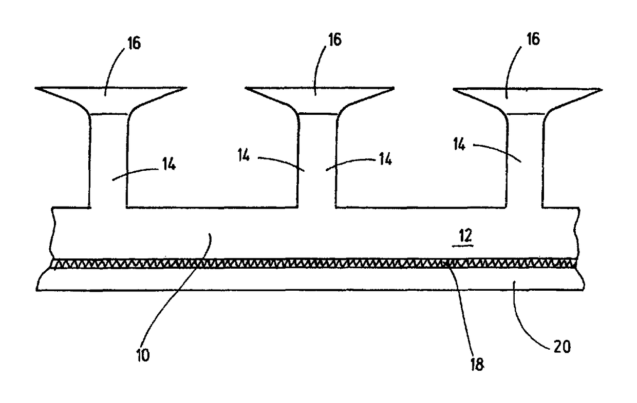
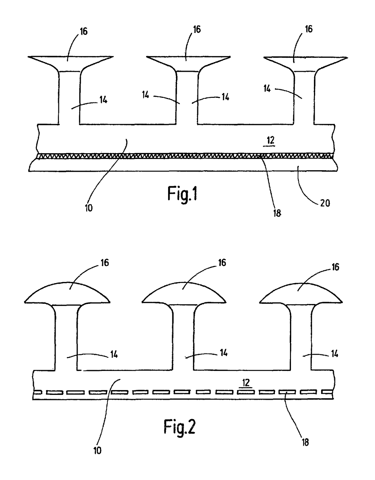
[0025]FIG. 1 shows a section of a functional part 10 having a substrate element 12 in the form of a substrate tape of predetermined length, transverse and height dimensions. Vertically protruding stem parts 14 are arranged on the substrate element 12, which stem parts widen towards their upper free ends and form head parts 16. Head parts 16 are integrally connected to the allocatable stem parts 14. The relevant stem parts 14, along with the head parts 16, form from the individual functional elements of the functional part 10.

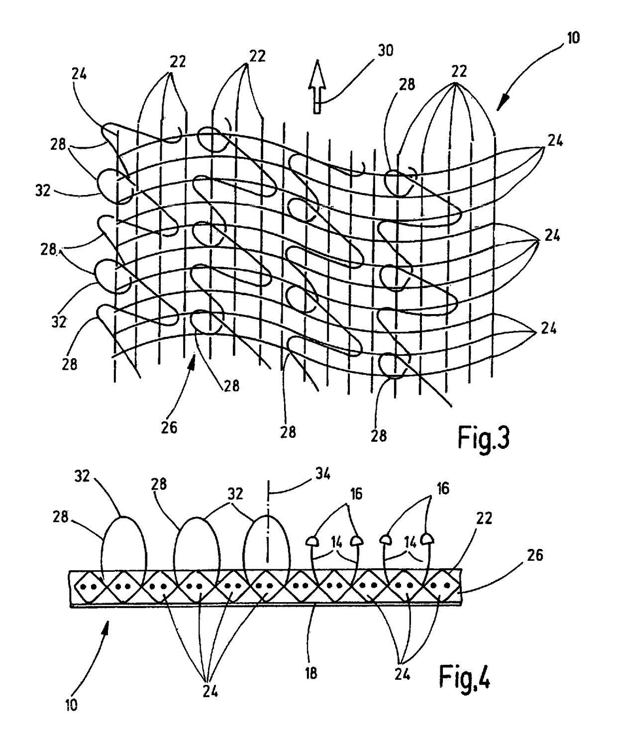
[0026]Such functional part 10 can be produced by a micro-replication process as shown in DE 10 2004 012 067 A1, by way of an example. The functional part shown in FIG. 1 forms an adhesive part. The generated functional element structure is very small, i.e. there may be more than 16,000 functional elements per square centimeter on the tape-shaped substrate 12. In particular, the functional elements in the plane of projection extend not only in the longitudinal di...


PUM

PropertyMeasurementUnit
Adhesion strengthaaaaaaaaaa
Adhesivityaaaaaaaaaa
Permeabilityaaaaaaaaaa

Abstract

A connection method, in addition to a functional part used in it and to a flame-retardant total system, connects a single- or multilayer functional part (10) to a third component (20). The functional part (10) has functional elements (14, 16) projecting on one side. The functional part (10) is formed at least partially from a material at least partially transparent to laser light. A blocking layer (18) is disposed to be at least partially opaque to laser light such that after passage of the laser light through the functional part (10), the laser light inside the blocking layer (18) generates heat by absorption for melting the functional part (10) and / or the third component (20) to connect them to one another.

Description

FIELD OF THE INVENTION[0001]The invention relates to a method for connecting a single or multi-layer functional part to a third component. The functional part has functional elements protruding on at least one side. The invention further relates to a functional part, in particular provided for use in such a bond method and a flame-retardant total system, particularly using the joining method and particularly by using the functional part.BACKGROUND OF THE INVENTION[0002]EP-B-0 883 354 discloses a flame retardant functional part, in particular a closure part adapted for releasable engagement to a second closure part, comprising:[0003]a tape-shaped substrate element made of a flame retardant polymeric material having an exposed bonding surface and a support surface;[0004]a multiplicity of flexible, resilient stem portions as functional elements, extending generally perpendicular to the bonding surface, the distal stem portions having enlarged head portions located on distal ends of the...

Claims


Application Information

Patent Timeline
IPC IPC(8): B29C65/16B29C65/00A44B18/00B29C65/48B29C65/72B29K55/02B29K69/00B29K81/00B29K105/16B29L31/00
CPCB29C65/1635A44B18/0092B29C65/1609B29C65/1616B29C65/1677B29C65/1683B29C65/483B29C65/484B29C65/72B29C66/1122B29C66/3452B29C66/45B29C66/723B29C66/72141B29L2031/775B29L2031/729B29K2995/0016B29K2105/167B29K2081/04B29C65/1664B29C65/485B29C66/472B29C66/5326B29C66/71B29K2055/02B29K2069/00B29C65/168B29K2995/0027
Inventor POULAKIS, KONSTANTINOS
Owner GOTTLIEB BINDER
Why Eureka
Try Eureka