Light emitting device having circuit protection unit
a light emitting device and protection unit technology, applied in the direction of lasers, basic electric elements, semiconductor lasers, etc., can solve the problems of high manufacturing cost, complex packaging process and insufficient protection of light emitting devices by circuit protection units, so as to prevent or mitigate excess forward current, reduce manufacturing complexity and cost, and prevent electrostatic damage
- Summary
- Abstract
- Description
- Claims
- Application Information
AI Technical Summary
Benefits of technology
Problems solved by technology
Method used
Image
Examples
third embodiment
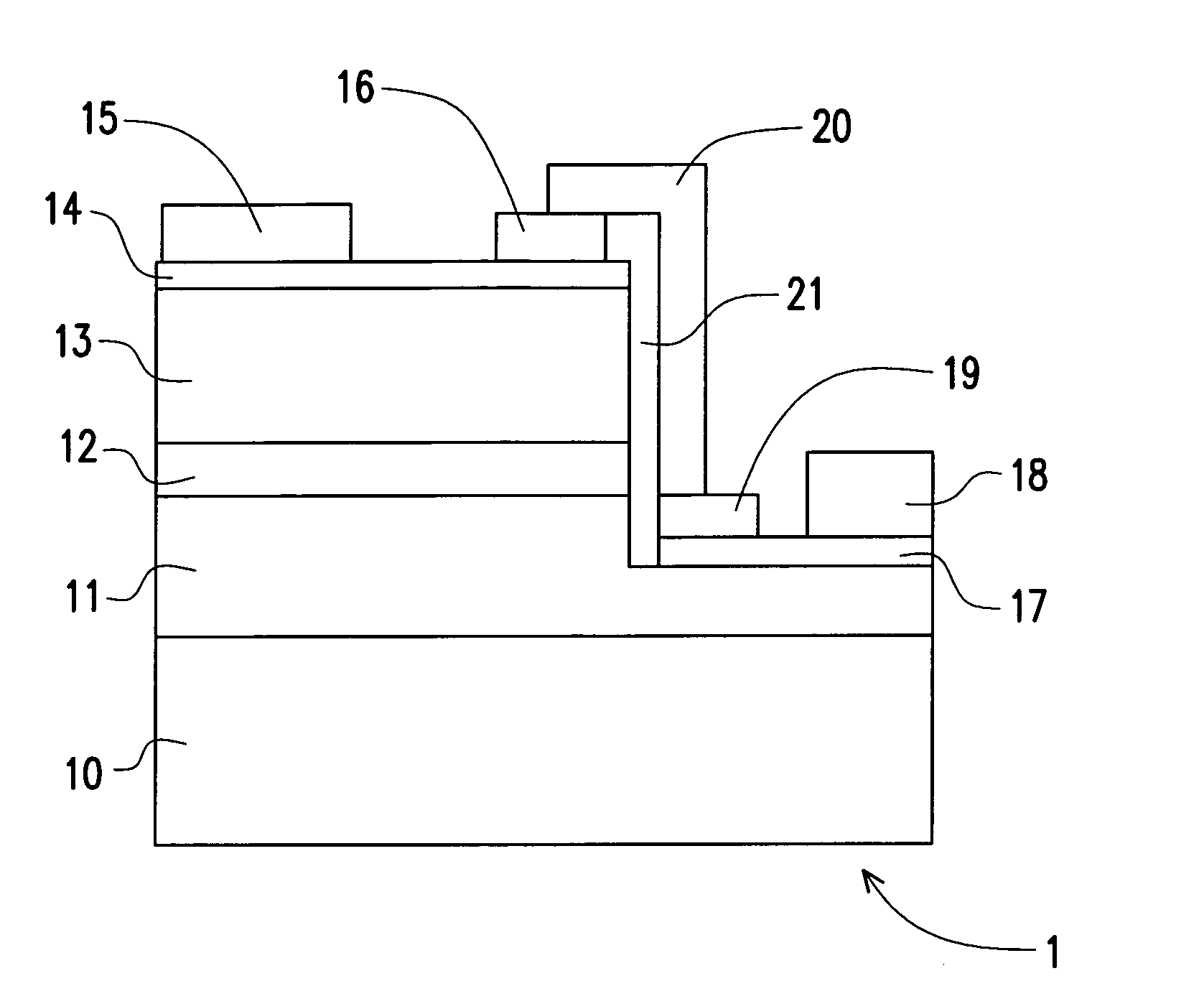
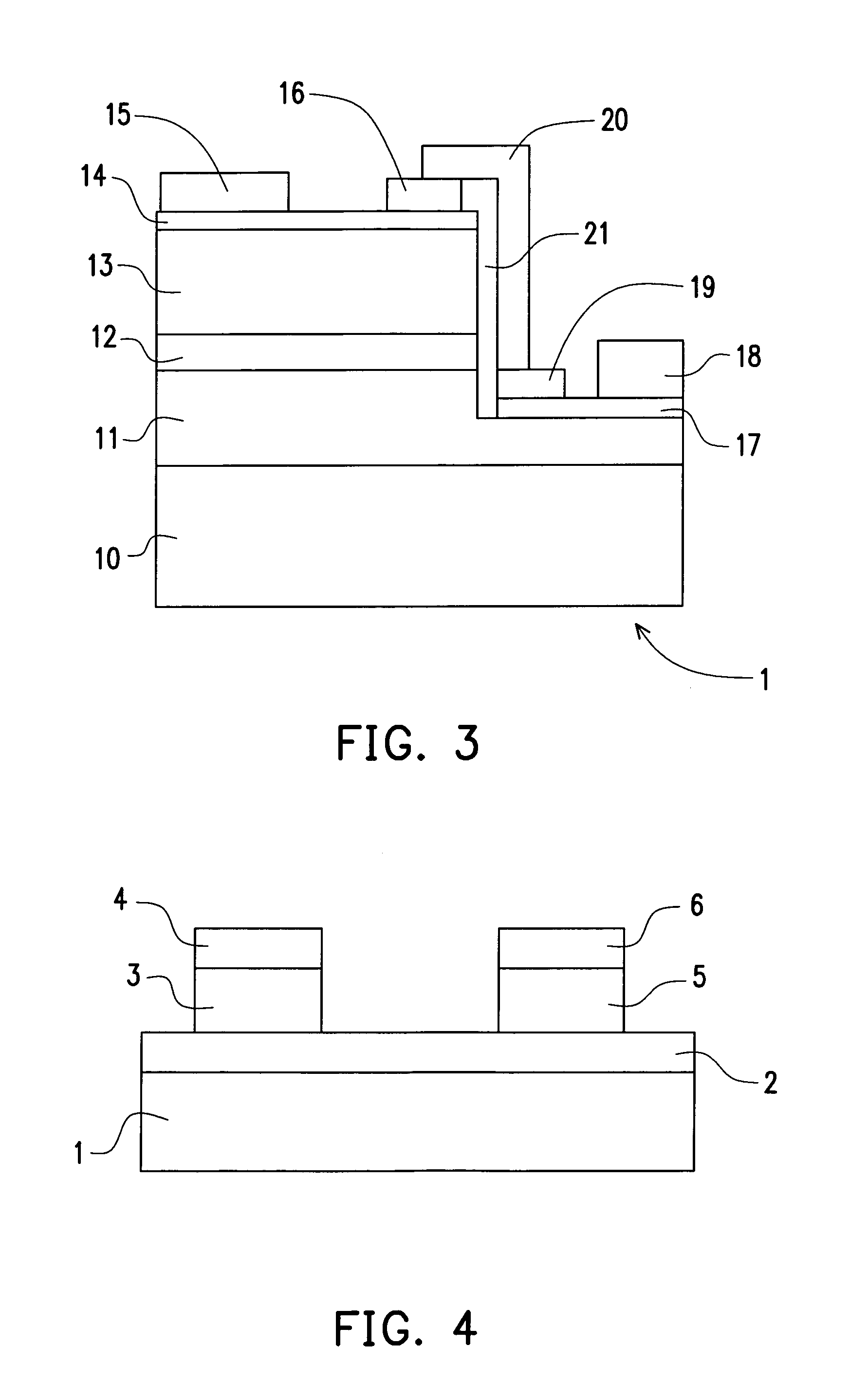
[0044]Referring to FIG. 7, the third light emitting device 3 having circuit protection unit, in accordance with the present invention, is illustrated. It should be noted that identical numericals represent the same elements in FIGS. 3FIG. 7. Therefore, description related to these elements is omitted here. In the light emitting device 3 as shown in FIG. 7, a bonding layer 310 is provided between the substrate 10 and the first stacking layer 11. The first stacking layer 11 is adhered onto the substrate 10 by wafer bonding technology.
[0045]In another embodiment of the present invention, the substrate 10 and the first stacking layer 11 are bonded directly under rising temperature and pressure without using the bonding layer 301. After the substrate 10 and the first stacking layer 11 are bonded directly under rising temperature and pressure, the first electrode and second electrode is disposed on opposite sides of the light emitting device. The layout of the circuit protection unit is d...
fourth embodiment
[0047]As shown in FIG. 8, the fourth light emitting device 4 having circuit protection unit, in accordance with the present invention, is illustrated. It should be noted that identical numericals represent the same elements in FIGS. 38. Therefore, description related to these elements is omitted here. In the fourth light emitting device 4, a conductive substrate 40 is used for replacing the substrate 10 shown in FIG. 3. Furthermore, a second electrode 48 disposed on a lower surface of the conductive substrate 40 is used for replacing the first electrode 18 shown in FIG. 3. The fourth light emitting device 4 having the conductive substrate 40 and the second electrode 48 is an LED of a vertically arranged structure.
[0048]In the fourth light emitting device 4, the second low-resistance layer 17 and the second potential barrier layer 19 is disposed on the first stacking layer 11. In other words, the first stacking layer 11 and the second electrode 48 are disposed on opposite sides of th...
PUM
 Abstract
Description
Claims
Application Information
 - R&D
- Intellectual Property
- Life Sciences
- Materials
- Tech Scout
- Unparalleled Data Quality
- Higher Quality Content
- 60% Fewer Hallucinations
Browse by: Latest US Patents, China's latest patents, Technical Efficacy Thesaurus, Application Domain, Technology Topic, Popular Technical Reports.
© 2025 PatSnap. All rights reserved.Legal|Privacy policy|Modern Slavery Act Transparency Statement|Sitemap|About US| Contact US: help@patsnap.com


