
Low power compact peak detector with improved accuracy

a detector and compact technology, applied in the field ofpeak detectors, can solve the problems of peak measurement error of up to 3 decibels below the actual peak level, and achieve the effect of reducing the amount of error and minimizing the error

Active Publication Date: 2018-07-24
SILICON LAB INC
View PDF5 Cites 2 Cited by
  • Summary
  • Abstract
  • Description
  • Claims
  • Application Information

AI Technical Summary

Benefits of technology

The patent text describes a technical solution for reducing errors in a circuit that receives input signals. The solution involves using five input transistors that have a gate overdrive voltage that is equal to a target peak voltage of the input signals. This results in a more accurate output signal even when the actual peak voltage is not perfectly aligned with the target level. Compared to conventional configurations, this solution minimizes errors and improves the accuracy of the output signal.

Problems solved by technology

In a conventional peak detector including two different 2-input peak detectors, this may cause a peak measurement error of up to 3 decibels below the actual peak level (i.e., the “3 dB down point”), which is of particular concern when the period of the input signal is high compared to the observation window of the peak detector.

Method used


Image

  • Low power compact peak detector with improved accuracy
  • Low power compact peak detector with improved accuracy
  • Low power compact peak detector with improved accuracy

Examples


Embodiment Construction

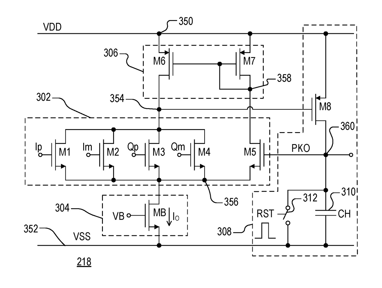
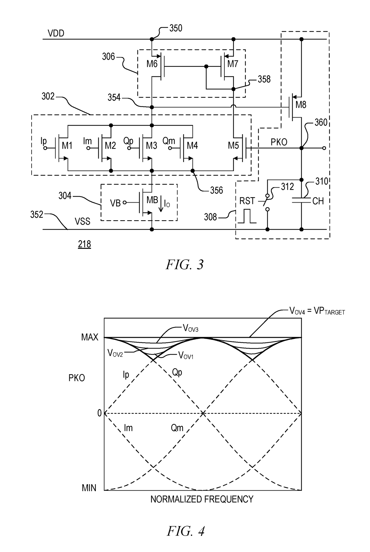
[0016]The inventor has recognized the need to improve the accuracy of peak detectors, including those used in an AGC loop of a receiver. He has also recognized the ongoing need for efficiency in terms of an electronic circuit implementation and power consumption. He has therefore developed a low power compact peak detector with improved accuracy. The inventor has developed a 4-input peak detector that is about the same size as the conventional 2-input peak detector and that draws the same level of current. The 4-input peak detector thus replaces the function of two separate conventional peak detectors thereby cutting both area and power consumption in half. Also, the novel 4-input peak detector significantly increases tracking bandwidth thus allowing accurate peak measurement for higher frequency signals. Furthermore, even when the signal is observed at or near the lowest point, accuracy is substantially improved as compared to the conventional configuration.

[0017]FIG. 1 is a simpli...


PUM


Abstract

A peak detector including an input circuit with five same-sized transistors, in which four of the input transistors are coupled in parallel between a control node and a bias node and receive a corresponding one of two in-phase signals and two quadrature signals. The fifth transistor is coupled between a current node and the bias node and has its control terminal coupled to an output node. A bias circuit establishes a predetermined bias current that flows through the five input transistors. A current mirror mirrors the current through the fifth transistor from the current terminal into the four parallel-coupled input transistors via the control node. An output circuit charges a peak capacitor based on voltage developed at the control terminal of the fifth transistor. The peak detector is low power and compact and detects the actual peak of the input signal with greater accuracy compared to a conventional peak detector.

Description

BACKGROUND OF THE INVENTIONField of the Invention[0001]The present invention relates in general to peak detectors, and more particularly to a peak detector that consumes less space and power, that has wider tracking bandwidth, and that detects the actual peak with improved accuracy.Description of the Related Art[0002]A peak detector is often used in the receiver chain of various communication products using either wired or wireless communications. It may be used, for example, as part of an automatic gain control (AGC) loop for ensuring the signal level of a received wireless signal is near a target level. In many communication systems, a received radio frequency (RF) signal is downconverted by the receiver to an intermediate frequency (IF) signal, which is then downconverted to a baseband signal. In other system configurations, the RF signal may be directly downconverted to baseband. In either case, one or more comparators may be used to compare in-phase (I) or quadrature pase (Q) d...

Claims


Application Information

Patent Timeline
Patent Type & Authority Patents(United States)
IPC IPC(8): H03D1/00H04L27/06H03K5/1532H03G3/20H04B1/16
CPCH03K5/1532H03G3/20H04B1/16G01R19/04H03G3/3052H03G2201/202H03G2201/302
Inventor COBAN, ABDULKERIM L.
Owner SILICON LAB INC
Learn More