Compressive sensing systems and related methods

a sensing system and compression technology, applied in the field of data processing systems, can solve the problems of reducing the ability to sample and process data, increasing the power consumption of processors by 2, and reducing the power/energy efficiency of processors, so as to reduce the dimensionality sequence and reduce the dimensionality

Active Publication Date: 2018-07-03
THE ARIZONA BOARD OF REGENTS ON BEHALF OF THE UNIV OF ARIZONA
View PDF20 Cites 4 Cited by
  • Summary
  • Abstract
  • Description
  • Claims
  • Application Information

AI Technical Summary

Benefits of technology

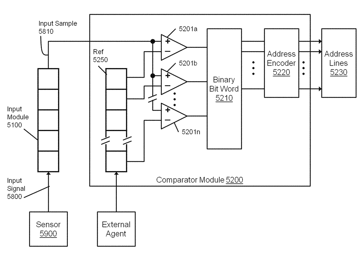
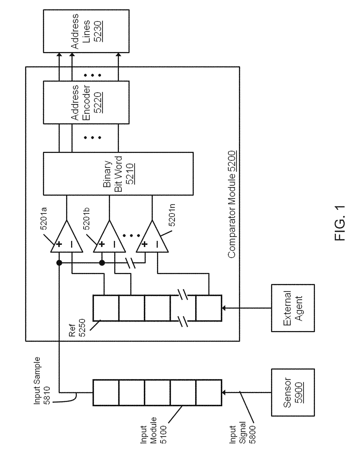
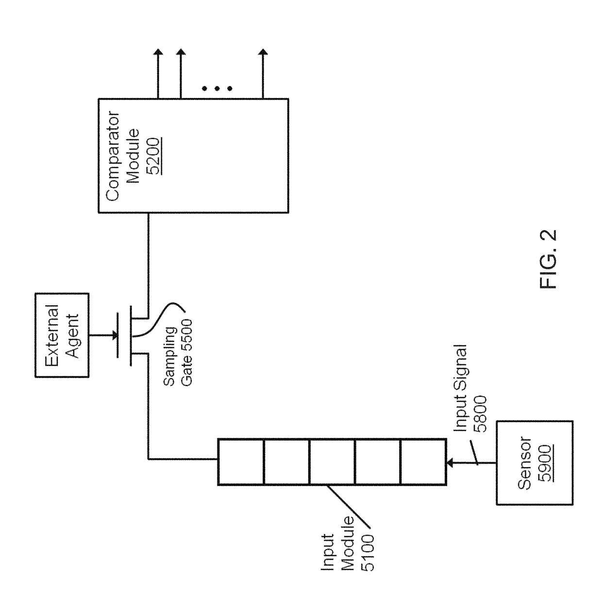
[0017]According to another embodiment, the present invention features a system to transform an input signal presented to a module that performs compressive sampling of the signal in real-time. The system may comprise an input module configured to divide the input signal into a sequence of signal values and present them in order of production to the following stages through a sampling gate which is controlled by gating element on-off values held in the following memory module to effect random sparse sampling in time; a comparator module coupled to the input module through the sampling gate and configured to accept each gated input element value of the sequence of signal values, the comparator module comprises a multiplicity of individual comparators which generate binary values assembled into a word of bits whose word value correlates the sequence element value with a vector of reference values to effect a level crossing sampler, and which assembled value is utilized to encode a memory address, each reference value of the reference value vector being fed to a corresponding one of the individual comparators; a memory module coupled to the comparator module through an address encoder, configured to select an ordered collection of pre-computed basis vectors scaled by the signal amplitude level implied by the address encoding to form one

Problems solved by technology

Power is one of the biggest challenges facing the semiconductor industry because every generation of CPU uses about twice as much power as the previous one.
For every generation of high end CPU, the power consumption increases by 2×.
Whi

Method used


Image

  • Compressive sensing systems and related methods
  • Compressive sensing systems and related methods
  • Compressive sensing systems and related methods

Examples


Embodiment Construction

[0040]The present disclosure will be better understood from reading the detailed description of examples of embodiments herein, taken in conjunction with the accompanying figures.

[0041]For simplicity and clarity of illustration, the figures illustrate the general manner of construction, and descriptions and details of well-known features and techniques may be omitted to avoid unnecessarily obscuring the invention. Additionally, elements in the figures are not necessarily drawn to scale. For example, the dimensions of some of the elements in the figures may be exaggerated relative to other elements to help improve understanding of embodiments of the present invention. The same reference numerals in different figures denote the same elements.

[0042]The terms “first,”“second,”“third,”“fourth,” and the like in the description and in the claims, if any, are used for distinguishing between similar elements and not necessarily for describing a particular sequential or chronological order. I...


PUM


Abstract

A system to transform an input signal presented from a sensor into a spatial sequence characteristic of the signal. An input module of the system is configured to divide the input signal into a sequence of signal values and present them in order of production to the following stage. A comparator module coupled to the input module configured to accept each element value of the sequence of signal values. The comparator module has a multiplicity of individual comparators that generate binary values assembled into a word of bits. The word value correlates the input sequence element value with a vector of reference values to effect a level crossing sampler. The assembled word value is utilized to encode a memory address. The system effects the conversion of a signal into an ordered collection of spatial values, which are the addresses of memory locations.

Description

CROSS REFERENCE[0001]This application is a continuation-in-part and claims benefit of PCT Application No. PCT / US15 / 24351 filed Apr. 3, 2015, which claims benefit of U.S. Provisional Patent Application No. 61 / 975,374, filed Apr. 4, 2014, the specification(s) of which is / are incorporated herein in their entirety by reference.FIELD OF THE INVENTION[0002]The present invention relates to data processing systems, and relates, more particularly, to compressive sensing systems and related methods.BACKGROUND OF THE INVENTION[0003]Power is one of the biggest challenges facing the semiconductor industry because every generation of CPU uses about twice as much power as the previous one. Researchers are exploring new ideas at various design stages to solve this issue. While we believe that most of the existing ideas in low power VLSI design are valid, we also need to focus on how we sample the external objects, extract the features, and process the data. Here, we provide a completely different a...

Claims


Application Information

Patent Timeline
IPC IPC(8): G06F13/38G06F1/32H03M1/34H03M1/12G06F13/42G09G5/00
CPCG06F13/42G09G5/003G06F1/3234G09G2330/021H03M7/3062Y02D10/00
Inventor WANG-ROVEDA, JANET M.POWERS, LINDA S.
Owner THE ARIZONA BOARD OF REGENTS ON BEHALF OF THE UNIV OF ARIZONA
Why Eureka
Try Eureka