Eureka AIR delivers breakthrough ideas for toughest innovation challenges, trusted by R&D personnel around the world.

Detecting tools for combustion turbine transitory section renovation technique and renovation technique thereof

A technology for gas turbines and transition sections, applied to mechanical measuring devices, turbines, measuring devices, etc., can solve problems affecting normal production, heavy economic burden on users, difficulty in meeting quality standards, etc., and achieve great practical value, strong standardization, and easy operation easy effect

Inactive Publication Date: 2007-07-04
SHENYANG DALU LASER TECH
View PDF0 Cites 8 Cited by
  • Summary
  • Abstract
  • Description
  • Claims
  • Application Information

AI Technical Summary

Problems solved by technology

It is difficult to meet the quality standard by traditional repair methods, and manufacturers usually purchase parts from abroad for replacement or send them abroad for repair, which not only brings a great economic burden to users, but also affects normal production

Method used


Image

  • Detecting tools for combustion turbine transitory section renovation technique and renovation technique thereof

Examples


Embodiment 1

[0019] The process steps are as follows:

[0020] 1. Sand blowing. Clean dirt from the interior and exterior surfaces of the restoration.

[0021] 2. Non-destructive testing. Detect defects in the transition section, including cracks, corrosion, etc., and make detailed inspection records for deformation and wear failures.

[0022] 3. Make a special calibration model. For the transitional section that is deformed, measure other transitional sections that have the same shape as the deformed part, and make a shape-calibration template based on the measured position.

[0023] 4. Material analysis, confirmation of material, and selection of special powder for laser cladding (material properties after melting and casting are not lower than the performance requirements of the base material).

[0024] 5. Remove the fatigue layer from the burnt parts and cracks, and the cracks should be cleaned up.

[0025] 6. Laser casting. Laser welding is performed on cracks and ablation parts...

Embodiment 2

[0040] Example 2 Repair of a worn transition section around a sealing groove and a round hole

[0041] The process steps are as follows:

[0042] 1. Sand blowing. Clean dirt from the interior and exterior surfaces of the restoration.

[0043] 2. Non-destructive testing. Detect whether there are other defects such as cracks and corrosion in the transition section, and carry out detailed inspection records for failures such as deformation and wear.

[0044] 3. Make a special calibration model. For the transitional section that is deformed, measure other transitional sections that have the same shape as the deformed part, and make a shape-calibration template based on the measured position.

[0045] 4. Material analysis, confirmation of material, and selection of special powder for laser melting (the performance of the material after melting and casting is not lower than the performance requirements of the base material).

[0046] 5. Measure and record the width of the seali...


PUM

PropertyMeasurementUnit
diameteraaaaaaaaaa

Abstract

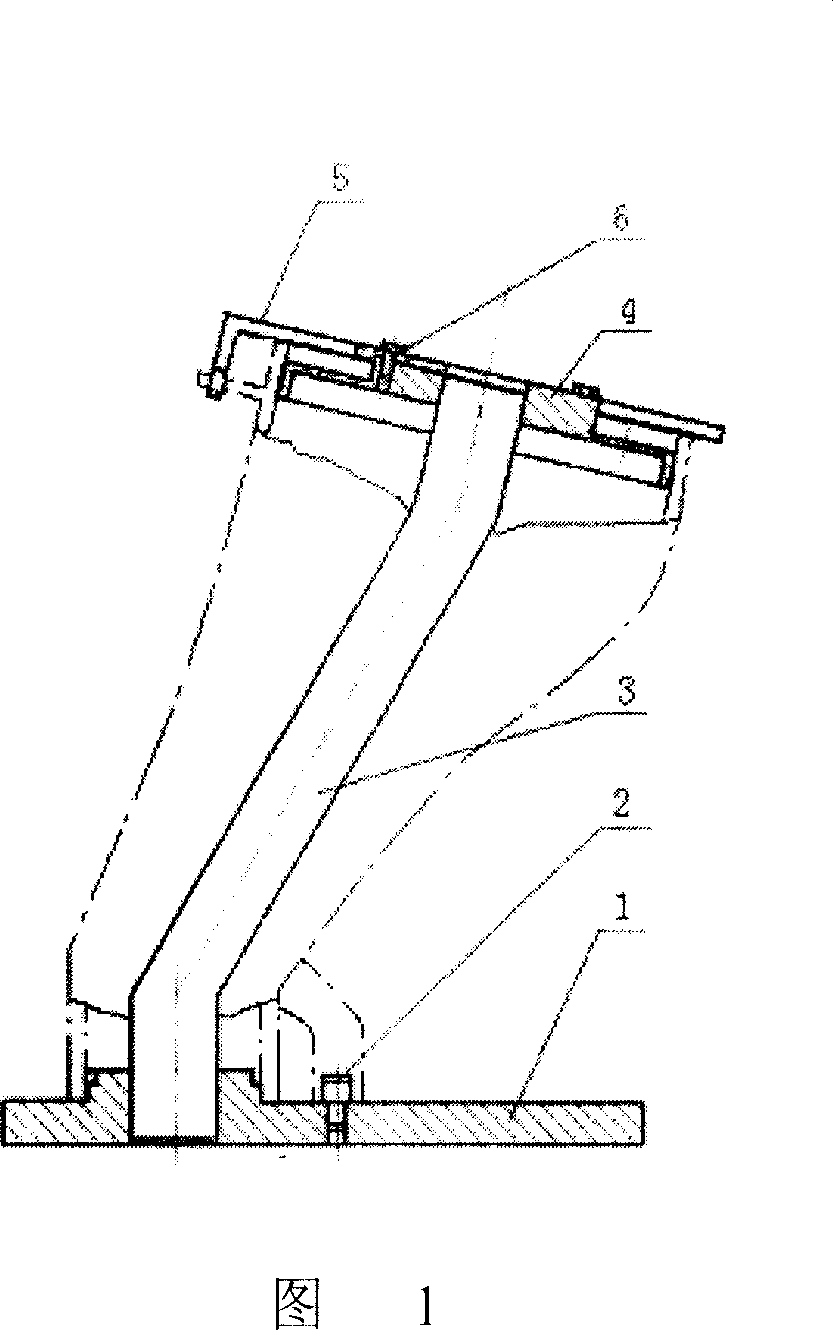
The invention provides detection equipment for gas turbine intermediate parts repair art which includes installation plate 1, straight pin 2, column 3, feeler gage main body 4, four feeler gage paws 5 and four bolts 6, one end of column 3 is fixed on the installation plate 1, and the other end is the positioning benchmark of feeler gage main body 4, the installation plate 1 is equipped with straight pin 2, four feeler gage paws 5 is fixed on the feeler gage main body 4 using hex bolts 6, its distribution angles is same and corresponding with the two distribution angles of intermediate part inlet gas end. The invention also provides repair art of intermediate parts, the process is: laser fusion casting: fusion pool diameter is 2~5mm, depth is 0.1~0.2mm, the heating time is 0.001 ~0.1 seconds, laser power is 500 ~ 2000W, laser scanning speed is 2~20mm / s; proofing shapes with jack; detecting with special equipment; spraying thermal barrier coatings on the inwall. The advantages of the process are: strong adaptability, simple operation, strong regulation, short repair cycle and less cost.

Description

technical field [0001] The invention relates to the repair and detection technology of gas turbine, especially the repair process of transition section of gas turbine. Background technique [0002] A gas turbine is a high-temperature, high-speed rotary machine used for power generation. It is a rotary heat engine that uses air and gas as working fluids. Its structure is mainly composed of three parts: compressor, combustion chamber and turbine. The combustion chamber is an important part that converts the chemical energy contained in the fuel into the internal energy of the working fluid. It is composed of a flame tube, a transition section, a fuel nozzle, a swirler, a cross-fire tube and other components. In layman's terms, the function of the combustion chamber is to convert the chemical energy contained in the fuel into the internal energy of the working fluid through chemical reactions. The specific performance is to increase the temperature of the working fluid, thereb...

Claims


Application Information

Patent Timeline
Patent Type & Authority Applications(China)
IPC IPC(8): B23P6/00B23K26/34G01B5/00G01B3/26
CPCF01D25/285B23P6/007B23K2201/001F05D2230/30B23K26/34B23K2101/001
Inventor 王蕴琦陈江刘豫
Owner SHENYANG DALU LASER TECH
Why Eureka
Eureka Blog
Learn More