
Open-end spinning device with an exchangeable twist congesting element

A holding element, rotor spinning technology, applied in the direction of continuous winding spinning machine, spinning machine, open-end spinning machine, etc., can solve problems such as uneven yarn, achieve high yarn quality and high flexibility performance, reducing downtime

Active Publication Date: 2007-06-13
RIETER INGOLSTADT SPINNEREI
View PDF3 Cites 4 Cited by
  • Summary
  • Abstract
  • Description
  • Claims
  • Application Information

AI Technical Summary

Problems solved by technology

If the arrangement of the doffing nozzle is off-centre with respect to the axis of the spinning rotor, it may cause uneven yarn after spinning

Method used


Image

  • Open-end spinning device with an exchangeable twist congesting element
  • Open-end spinning device with an exchangeable twist congesting element
  • Open-end spinning device with an exchangeable twist congesting element

Examples


Embodiment Construction

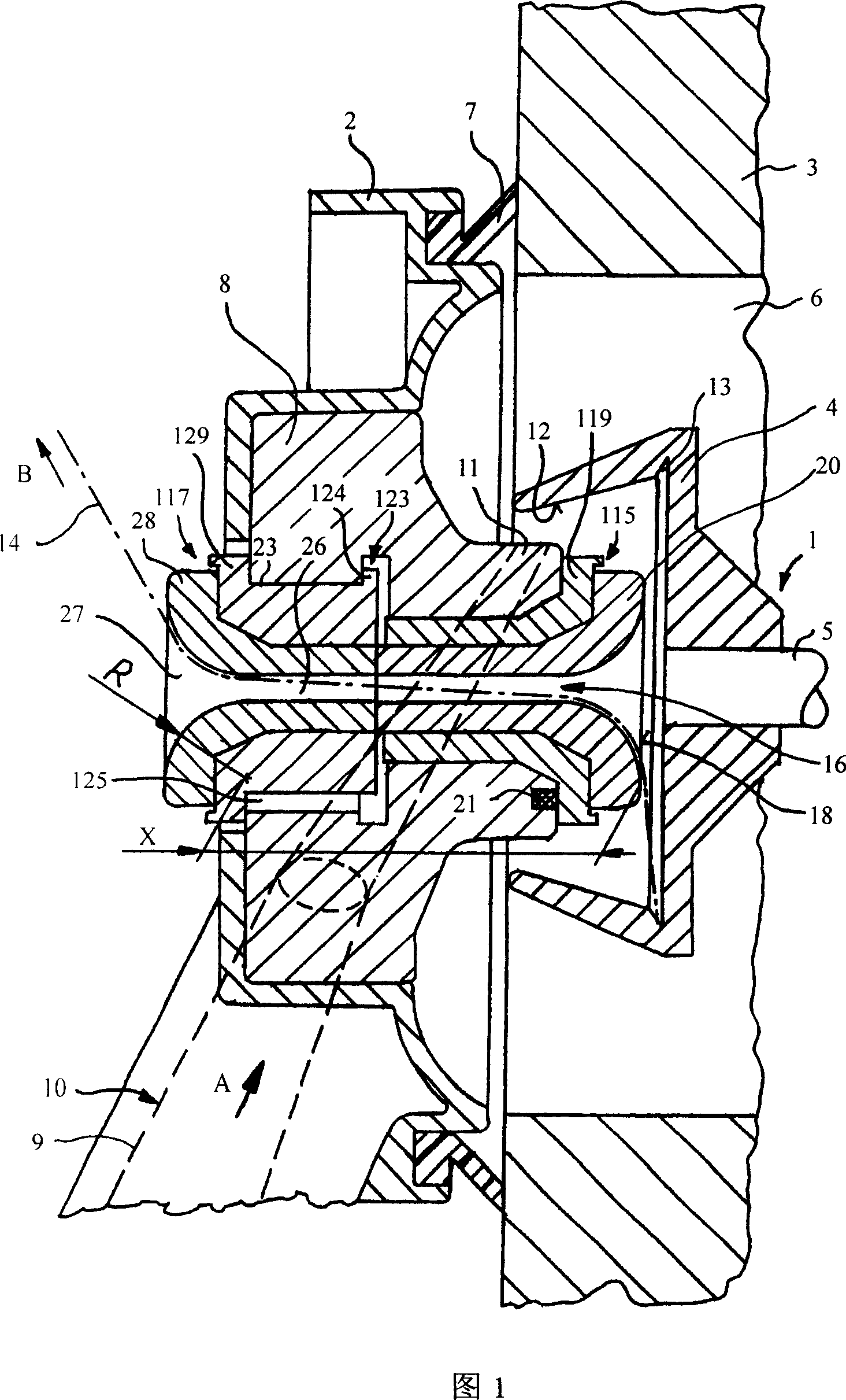
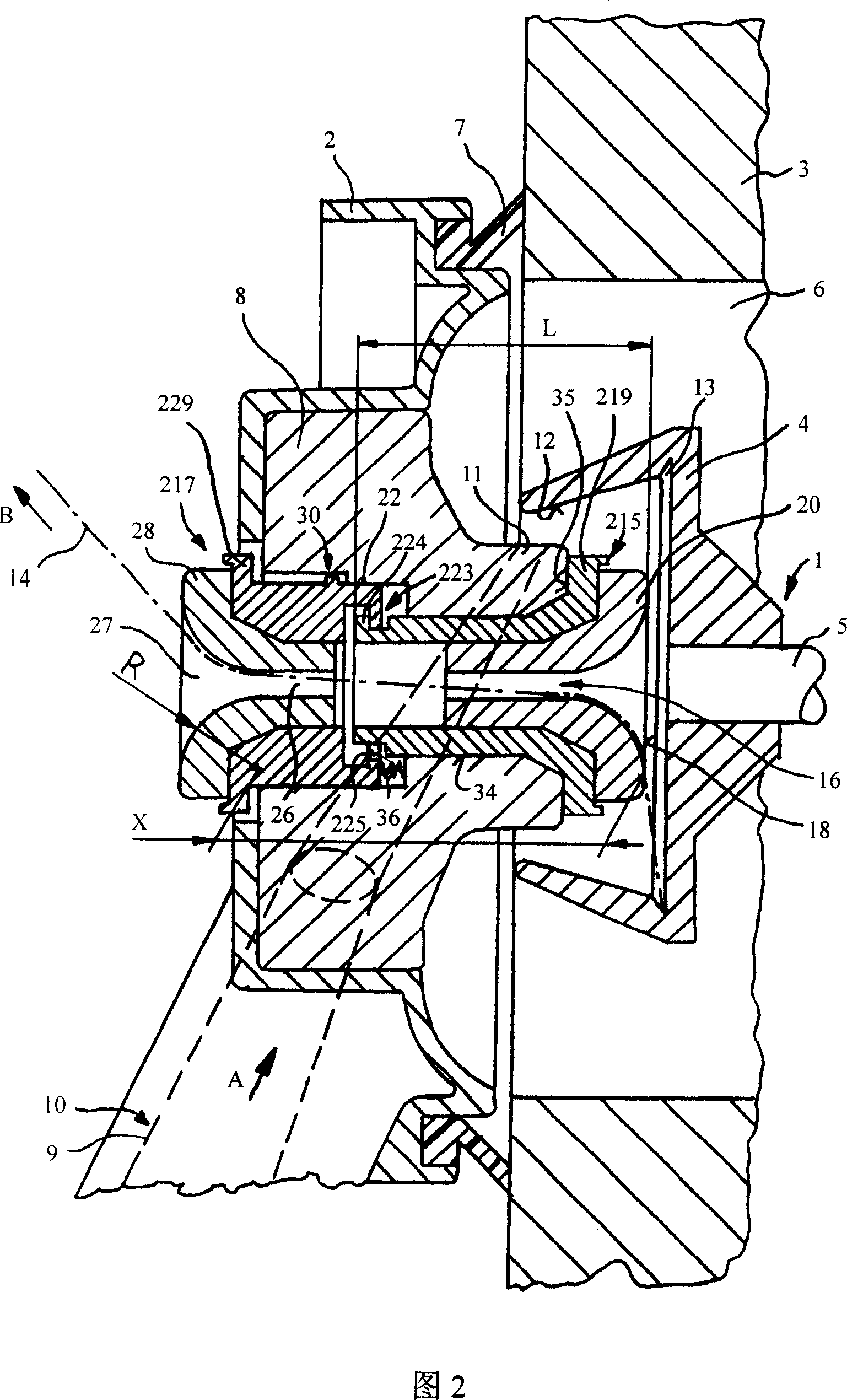
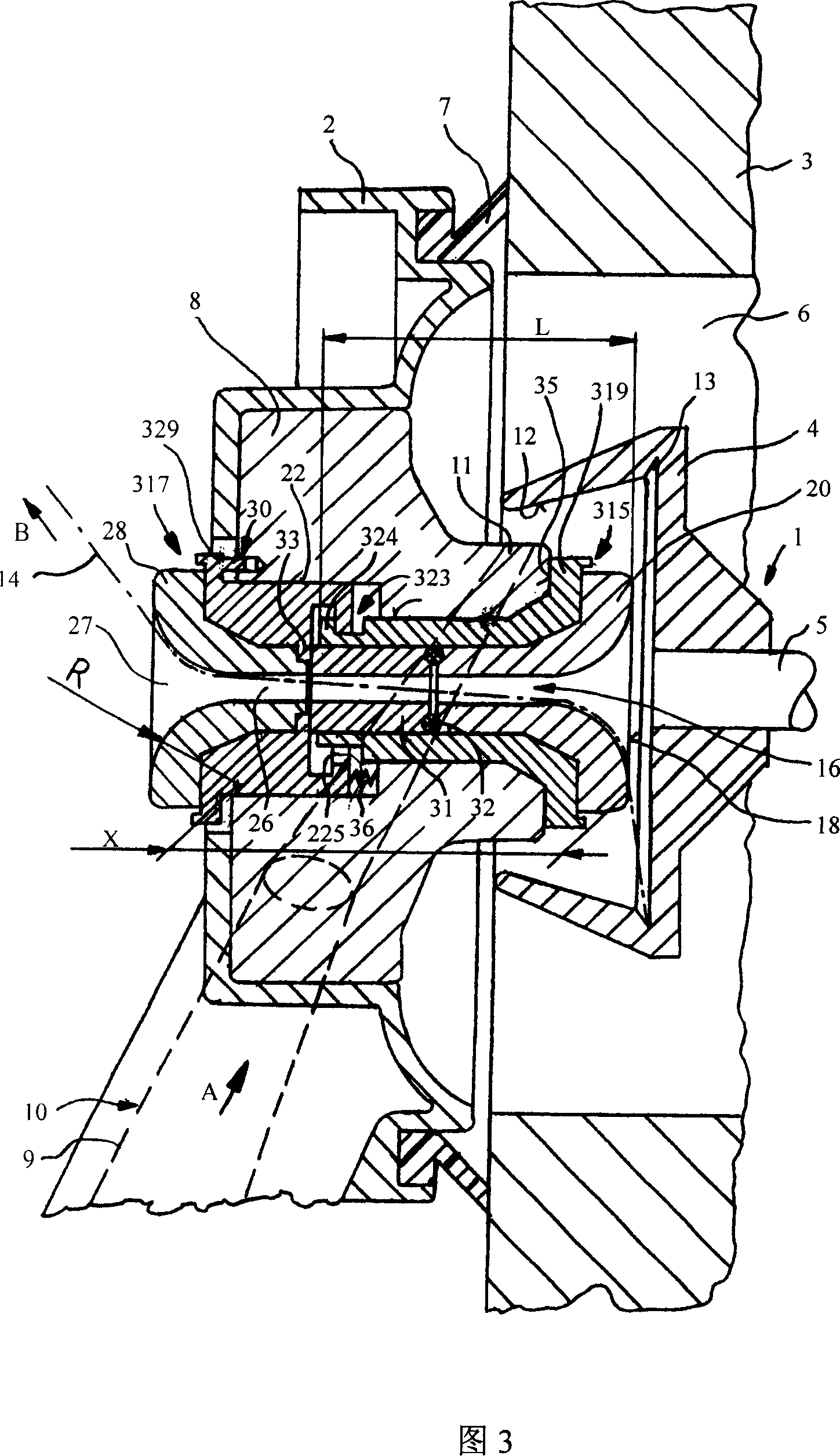
[0034] FIG. 1 shows a spinning rotor 1 enclosed in a rotor housing 3 by a cover 2 on a rotor spinning spinning device. The spinning rotor 1 is formed in a known manner from a rotor disk 4 and a shaft 5 supported and driven in a manner not shown in the figures.

[0035] In the operating state, the rotor disk 4 rotates in a known manner in a negative-pressure chamber 6 formed by the rotor housing 3 . During operation, the rotor housing 3 is closed with a cover 2 which can be removed for maintenance purposes. The sealing ring 7 is used for sealing between the cover 2 and the rotor housing 3 .

[0036] On the cover 2 , which is often designated as a bezel, a substantially rotationally symmetrical bezel adapter 8 is arranged as an exchangeable projection, which can protrude partially into the interior of the rotor disk 4 . A section 9 of a fiber feed trough 10 is arranged in the cover 2, the fiber feed trough 10 extends from the opening roller, not shown in the figure, to the rot...


PUM

PropertyMeasurementUnit
diameteraaaaaaaaaa
lengthaaaaaaaaaa

Abstract

A rotor spinning spinning device including a cover encloses rotor housing. A replaceble groove plate adapter is arranged in the cover to feed fibre and doff. Doffing is processed by a doffing nozzle and at least a easily changed holder part which arranged in the rear. The twiddle rotate holder has a doffing hole basically in the centre. The twiddle rotate holder inserts directly in the groove plate adapter.

Description

technical field [0001] The invention relates to a rotor spinning device with a twist-retaining element, which has a cover which closes the rotor housing, wherein the Fiber feeding and doffing, moreover, doffing via a doffing nozzle and at least one rearwardly arranged and easily replaceable twist-holding element with a doffing hole substantially in its center . [0002] In addition, the present invention also relates to a slot plate adapter suitable for the above-mentioned rotor spinning device, a doffing nozzle, and an independent assembly composed of the above-mentioned components. Background technique [0003] It has been known for a long time that spinning rotors of different diameters can be installed in rotor spinning spinning units. In order to adapt the fiber supply to different diameters, it is known, for example according to DE 19934893 A1, that a slot adapter can be easily inserted under the cover of the rotor housing and that the slot adapter contains the end s...

Claims


Application Information

Patent Timeline
Patent Type & Authority Applications(China)
IPC IPC(8): D01H4/08D01H4/40
CPCD01H4/40
Inventor M·布尔歇特S·克罗默尔B·洛斯
Owner RIETER INGOLSTADT SPINNEREI
Learn More