Cold heat exchanger
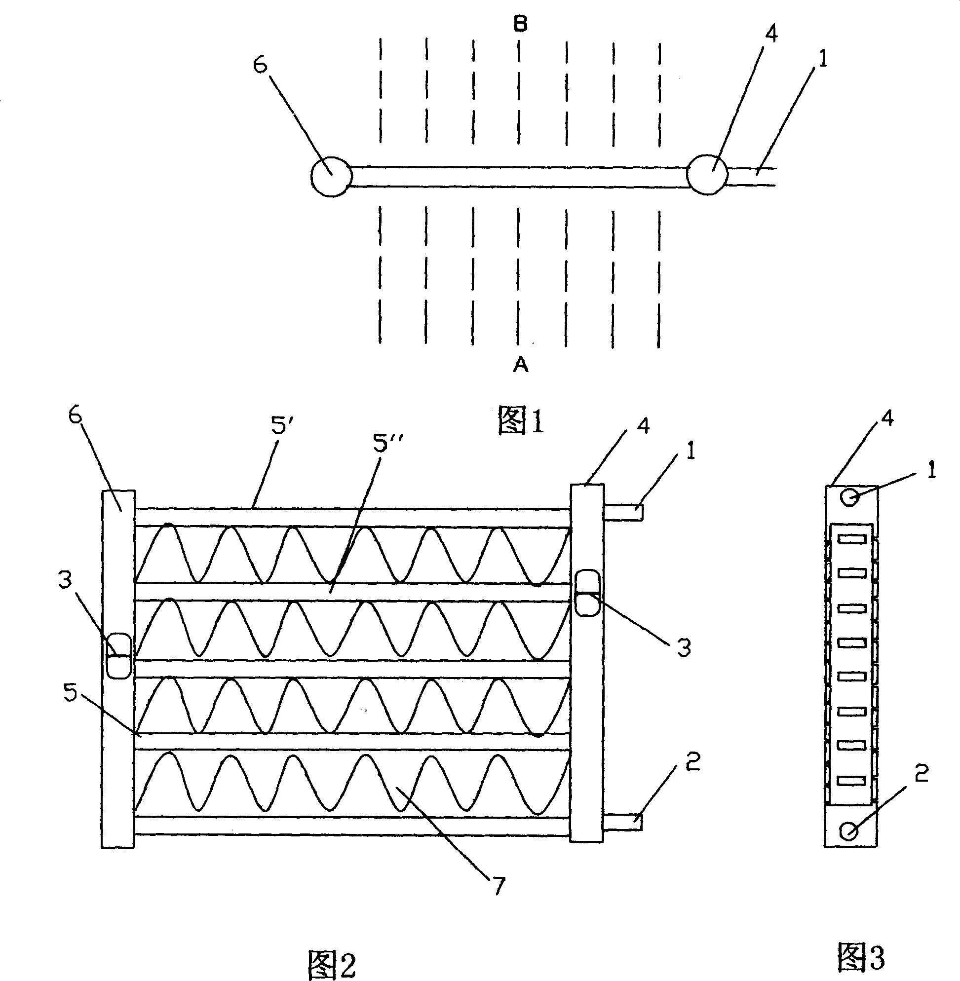
A cold and heat exchanger, cold and hot technology, applied in the direction of heat exchanger type, indirect heat exchanger, lighting and heating equipment, etc., can solve the problems of lamination width limitation, wide product thickness, many welding points, etc., to prevent oxidation , the effect of reducing airflow resistance and increasing the contact area
- Summary
- Abstract
- Description
- Claims
- Application Information
AI Technical Summary
Problems solved by technology
Method used
Image
Examples
Embodiment 1
[0113] Referring to Fig. 7, the first and second headers 1, 2 are located in the upper and lower positions of the flat tube units 3 parallel to each other; the flat tube units 3 parallel to each other are arranged in a row at certain intervals, and between adjacent flat tube units 3 The air flow side channel 5 , the outer fin 4 is located in the air flow side channel 5 .
[0114] The flat tube unit 3 is composed of two flat channel tubes 31 connected by a parallel part 311 , one flat channel tube 31 is located on the air inflow side, and the other flat channel tube 31 is located on the air outflow side.
[0115] In the first header 1 there are two separate and parallel headers 1a and 1b, in the second header 2 there is a header 2a, in the header of the first header 1 A partition 8 is provided at the middle position of the length direction of 1b, and the partition 8 divides the collector channel 1b into two parts, left and right. A partition 8 is provided at the middle positio...
Embodiment 2
[0120] Referring to FIG. 8 , baffles 10 are provided outside the left and right outermost flat tube units 3 to protect the flat tube units 3 . In the first header 1 there are two separate and parallel headers 1a and 1b, in the second header 2 there is a header 2a, in the header of the first header 1 A partition 8 is provided at the middle position of the longitudinal direction of 1a and 1b, and the partition 8 separates the collectors 1a and 1b into left and right parts respectively. The partitions 8 on the manifolds 1a and 1b can be in the same position or in different positions.
[0121] A plurality of partitions 8 are provided in the longitudinal direction of the collector channel 2a of the second header 2, and the plurality of partition plates 8 divide the collector channel 2a into a plurality of parts.
[0122] The outlet 7 and the inlet 6 of the refrigerant are respectively arranged on the left and right parts of the divider 8 in the collecting channel 1b of the first c...
Embodiment 3
[0126] Referring to Fig. 9, there are two separate and parallel collector channels 1a and 1b in the first header 1, and two separate and parallel collector channels 2a and 1b in the second header 2. 2b, a partition 8 is provided at the right position in the longitudinal direction of the collectors 1a and 1b of the first header 1, and the partition 8 divides the collectors 1a and 1b into left and right parts, the collectors 1a and 1b 1b The right parts of the two are connected. A partition 8 is provided at the left position of the collector channel 2b of the second header 2 in the length direction, and the partition plate 8 divides the collector channel 2b into left and right parts, wherein the right part is more than the left part.
[0127] The refrigerant inlet 6 is arranged at the left end of the collecting channel 1 a of the first header 1 , and the outlet 7 is arranged at the left end of the collecting channel 2 b of the second header 2 . All the other structures are with...
PUM
 Abstract
Description
Claims
Application Information
 - R&D Engineer
- R&D Manager
- IP Professional
- Industry Leading Data Capabilities
- Powerful AI technology
- Patent DNA Extraction
Browse by: Latest US Patents, China's latest patents, Technical Efficacy Thesaurus, Application Domain, Technology Topic, Popular Technical Reports.
© 2024 PatSnap. All rights reserved.Legal|Privacy policy|Modern Slavery Act Transparency Statement|Sitemap|About US| Contact US: help@patsnap.com


