Fuel injection system designed to ensure enhanced reliability of diagnosis of valve

A fuel injection system and fuel technology, applied in the field of systems, can solve problems such as inability to discharge fuel, etc.

Inactive Publication Date: 2007-04-11
DENSO CORP
View PDF3 Cites 15 Cited by
  • Summary
  • Abstract
  • Description
  • Claims
  • Application Information

AI Technical Summary

Problems solved by technology

[0008] However, typical pressure reducing valves may lock up in the closed state due to improper operation of the valve actuator and thus not properly vent fuel from the common rail.

Method used


Image

  • Fuel injection system designed to ensure enhanced reliability of diagnosis of valve
  • Fuel injection system designed to ensure enhanced reliability of diagnosis of valve
  • Fuel injection system designed to ensure enhanced reliability of diagnosis of valve

Examples


Embodiment Construction

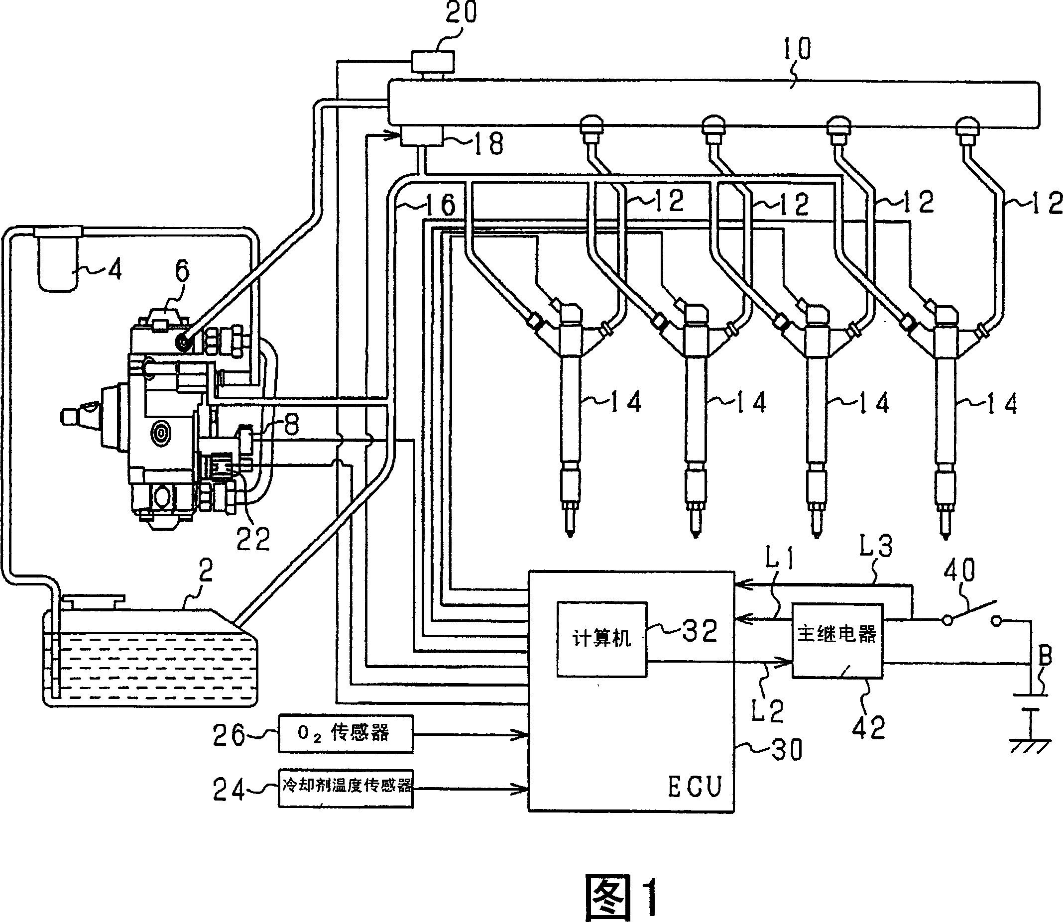
[0038]Referring to the drawings, wherein like reference numerals refer to like parts in the several views, and especially to FIG. Common rail fuel injection system (also known as cumulative injection system) for diesel engine injection fuel.

[0039] The fuel injection system includes a fuel pump 6 , a common rail 10 , a fuel injector 14 , a pressure reducing valve 18 and an electronic control unit (ECU) 30 .

[0040] The fuel pump 6 operates, draws fuel from the fuel tank 2 through the fuel filter 4 and supplies it to the common rail 10 . The fuel pump 6 is driven by the torque of the crankshaft of the diesel engine. In particular, the fuel pump 6 is equipped with a suction control valve 8 activated by the ECU for determining the amount of fuel discharged from the fuel pump 6 . The fuel pump 6 is also equipped with a plurality of plungers (or pistons) that reciprocate between top dead centers and bottom dead centers to suck fuel from and discharge fuel to the common rail 10...


PUM


Abstract

A fuel injection system for automotive diesel engine is provided which is equipped with a fuel pressure sensor working to measure the pressure of fuel in an accumulator and a pressure-reducing valve working to drain the fuel from the accumulator. The system is designed to ensure enhanced reliability of diagnosis of the pressure-reducing valve. The system works to make a temporal diagnosis of the pressure-reducing valve based on the behavior of the pressure in the accumulator upon opening of the pressure-reducing valve after an ignition switch is turned off. After elapse of a given period of time, when it is determined that a value of the pressure in the accumulator, as measured by the fuel pressure sensor, lies near the atmospheric pressure, the system determines that the fuel pressure sensor is operating properly and fixes the temporal diagnosis of the pressure-reducing valve ultimately.

Description

[0001] Cross References to Related Applications [0002] This application claims priority from Japanese Patent Application No. 2005-293153 filed on October 6, 2005, the disclosure of which is incorporated herein by reference. technical field [0003] The present invention relates generally to accumulator fuel injection systems equipped with a fuel pressure sensor for measuring the fuel pressure in an accumulator, such as a common rail, and a pressure reducing valve for reducing the pressure in the accumulator, and in particular to Such a system is designed to ensure an increased reliability of the diagnosis of the pressure relief valve. Background technique [0004] It is known that automotive fuel injection systems are equipped with a pressure accumulator (also called common rail) for supplying fuel at high pressure to the fuel injectors of each cylinder of a diesel engine. Such common rail fuel injection systems are generally designed to control the fuel pressure in the c...

Claims


Application Information

Patent Timeline
Patent Type & Authority Applications(China)
IPC IPC(8): F02M55/02
CPCF02M63/025F02D2250/31F02D41/3863F02M55/02F02D41/222F02D2041/223F02M63/0225F02D41/221F02D2200/0602F02M65/003
Inventor 高桥智宏
Owner DENSO CORP
Why Eureka
Try Eureka