
Novel phase change memory and its forming method

一种存储元件、相变化的技术,应用在电气元件、半导体器件、电固体器件等方向,能够解决复杂、高成本等问题,达到写入电流降低、降低制程复杂度及成本的效果

Active Publication Date: 2007-01-17
TAIWAN SEMICON MFG CO LTD
View PDF0 Cites 12 Cited by
  • Summary
  • Abstract
  • Description
  • Claims
  • Application Information

AI Technical Summary

Problems solved by technology

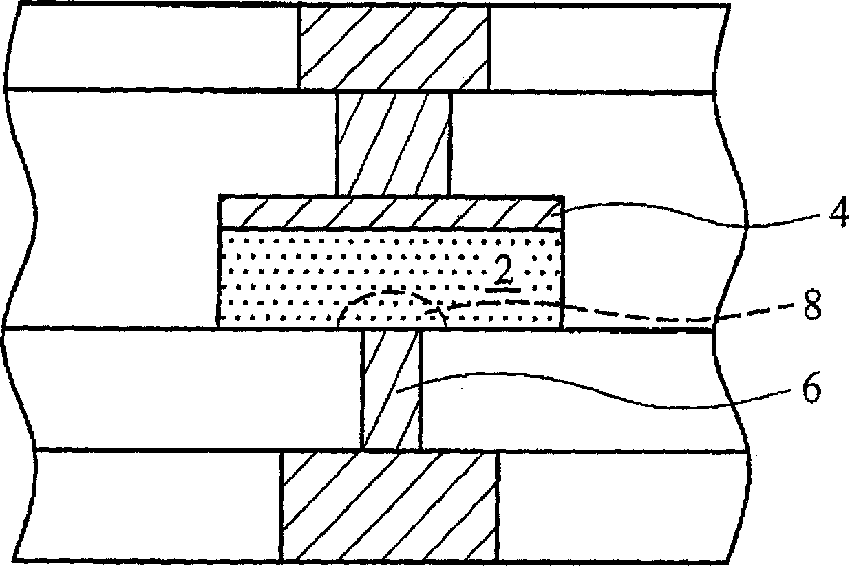
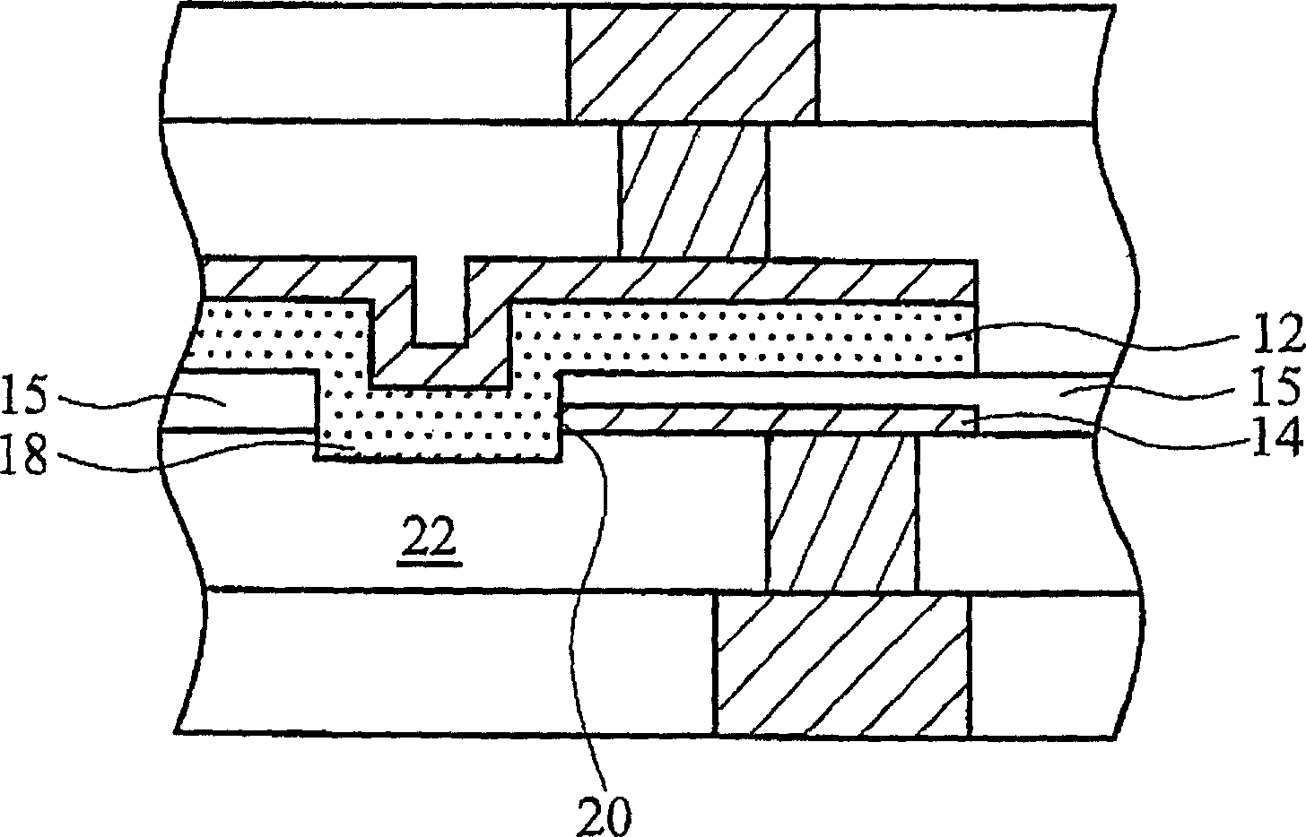
However, the above method requires complicated and high-cost processes, for example, in order to form the side contact region 20, after the bottom electrode 14 is deposited and patterned, the interlayer dielectric layer (ILD) 15 is then deposited.

Method used


Image

  • Novel phase change memory and its forming method
  • Novel phase change memory and its forming method
  • Novel phase change memory and its forming method

Examples


Embodiment Construction

[0030] In order to make the above and other objects, features, and advantages of the present invention more comprehensible, a preferred embodiment is specifically cited below, and is described in detail in conjunction with the accompanying drawings as follows:

[0031] Such as Figure 3A As shown, wires 32 and insulating layer 30 are formed in the first metallization layer. In a preferred embodiment, the wires 32 are formed by a metal etching process, and then the insulating dielectric layer 30 is formed, that is, an interlayer dielectric (ILD). The wire 32 can be a commonly used metal material, such as metal or metal alloy, including Al, AlCu, Cu, Ti, TiN or W. Conductor 32 forms part of a current drive circuit (not shown) to provide current to induce a phase change.

[0032] In other embodiments, such as Figure 3B As shown, the wire 32 is formed by a single damascene process, in which the insulating layer 30 is formed after patterning a photoresist (not shown), etching a...


PUM


Abstract

A phase change memory device with a reduced phase change volume and lower drive current and a method for forming the same are provided. The method includes forming a bottom insulating layer comprising a bottom electrode contact, forming a bottom electrode film on the bottom electrode contact, forming an anti-reflective coating (ARC) film on the bottom electrode film, patterning and etching the ARC film and the bottom electrode film to form a bottom electrode comprising a side edge, and forming a phase change material portion on the ARC film and the bottom insulating layer, wherein the phase change material portion physically contacts the side edge of the bottom electrode. The method further includes forming a top electrode on the phase change material portion, and forming a top electrode contact on the top electrode.

Description

technical field [0001] The present invention relates to a semiconductor device and its manufacturing process, in particular to a phase change random access memory device with small phase change volume and its manufacturing method. Background technique [0002] Phase change technology is the most developed storage method for next-generation storage devices. It utilizes a chalcogenide semiconductor as a storage material. Chalcogenide semiconductors, also known as phase change materials, have two types: crystalline and amorphous. Phase change materials have low electrical resistance in the crystalline state and high electrical resistance in the amorphous state. The resistance ratio of the phase change material in the crystalline state and the amorphous state is generally greater than 1000, so the phase change memory device is less prone to errors when reading the state. Chalcogenides are very stable in both crystalline and amorphous states over certain temperature ranges, an...

Claims


Application Information

Patent Timeline
Patent Type & Authority Applications(China)
IPC IPC(8): H01L45/00H01L27/24H01L21/82
CPCH01L45/04H01L45/06H01L45/144H01L45/126H01L45/1233H01L45/122H10N70/821H10N70/8413H10N70/231H10N70/826H10N70/8828
Inventor 黄健朝
Owner TAIWAN SEMICON MFG CO LTD
Learn More