Dc-Dc converter

A DC-DC and converter technology, applied in the field of DC-DC converters, can solve problems such as increased switching loss, inability to switch on/off switching units, and inability to obtain sufficient performance, and achieves low current value, design Easy, simplified effect

Inactive Publication Date: 2007-01-03
HONDA MOTOR CO LTD
View PDF1 Cites 12 Cited by
  • Summary
  • Abstract
  • Description
  • Claims
  • Application Information

AI Technical Summary

Problems solved by technology

As can be seen from this figure, when the on / off driving frequency of the switching unit 2 deviates from the resonance frequency of the resonant circuit 3, the on / off switching of the switching unit cannot be performed near the zero crossing of the resonance current, and thus Increased switching loss prevents sufficient performance

Method used


Image

  • Dc-Dc converter
  • Dc-Dc converter
  • Dc-Dc converter

Examples


Embodiment Construction

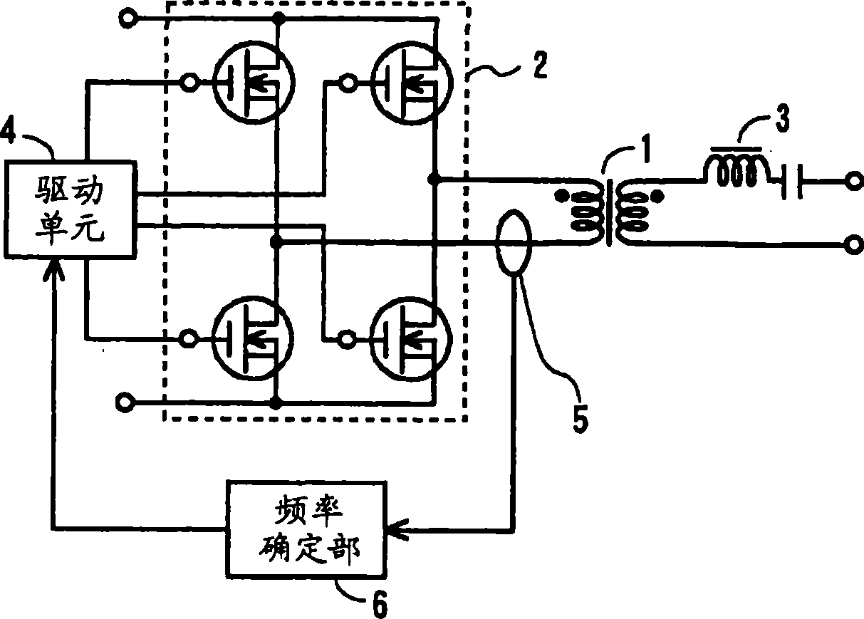
[0030] Hereinafter, the present invention will be described with reference to the drawings. figure 1 It is a circuit diagram showing the principle of the DC-DC converter of the present invention. Hereinafter, the same or equivalent parts as in FIG. 4 are denoted by the same symbols. figure 1 The difference from FIG. 4 is that a resonance current frequency detection unit for detecting the frequency of the resonance current generated by the operation of the resonance circuit 3 is provided, and the frequency detected by this unit is fed back to the drive unit 4 . The resonant current frequency detection unit is composed of the following parts: the resonant current detection current transformer 5, which is arranged, for example, on the line where the resonant current flows on the primary side of the transformer 1; The detection determines the frequency of the resonance current detected by the current transformer 5 .

[0031] below, yes figure 1 actions are described. The dr...


PUM


Abstract

There is provided a DC-DC converter capable of increasing the conversion efficiency by suppressing the switching loss by using a simple structure. An LC resonance circuit (3) is inserted to the secondary side of a transformer (1). When switching means (2) is driven ON / OFF by drive means (4), an output is obtained at the secondary side via the transformer (1). Resonance current frequency detection means includes a current-detecting current transformer (5) and a frequency detector (6) and detects a frequency of resonance current by operation of the LC resonance circuit (3). This frequency is fed back to the drive means (4). As a result, the drive means (4) drives ON / OFF the switching means (2) with a frequency matched with the resonance frequency of the LC resonance circuit (3).

Description

technical field [0001] The invention relates to a DC-DC converter, in particular to a DC-DC converter capable of suppressing switching loss and improving conversion efficiency. Background technique [0002] The DC-DC converter of the current resonance method has a resonant circuit connected in series with the switching unit, and the switching unit is turned on / off at the resonant frequency of the resonant circuit. FIG. 4 is a diagram showing the principle of a DC-DC converter. On the primary side of the transformer 1 is provided a switching unit 2 having, for example, a bridge structure of four switching elements, and a resonant circuit 3 is provided on the secondary side. The resonance circuit 3 is composed of a resonance choke coil (reactor) and a resonance capacitor. In addition, a rectification and smoothing unit is provided on the secondary side, but is not shown in the figure. [0003] When the switching unit 2 is driven on / off at the resonance frequency of the reso...

Claims


Application Information

Patent Timeline
Patent Type & Authority Applications(China)
IPC IPC(8): H02M3/28H02M3/155H02M1/10H02M3/335
CPCH02M1/10Y02B70/1475Y02B70/1441Y02B70/1433H02M7/5387H02M3/33592Y02B70/10H02M3/28
Inventor 江口博之清水元寿
Owner HONDA MOTOR CO LTD
Why Eureka
Try Eureka