
Stator of linear motor

A linear motor and stator technology, applied in the direction of electric components, electromechanical devices, electrical components, etc., can solve problems such as damage to insulation parts, achieve heat dissipation, small size, and improve insulation and heat transfer efficiency

Inactive Publication Date: 2006-11-22
LG ELECTRONICS INC
View PDF0 Cites 10 Cited by
  • Summary
  • Abstract
  • Description
  • Claims
  • Application Information

AI Technical Summary

Problems solved by technology

As a result, damage to the insulation

Method used


Image

  • Stator of linear motor
  • Stator of linear motor
  • Stator of linear motor

Examples


Embodiment Construction

[0049] Now, referring to the accompanying drawings, preferred embodiments of the present invention will be described in detail.

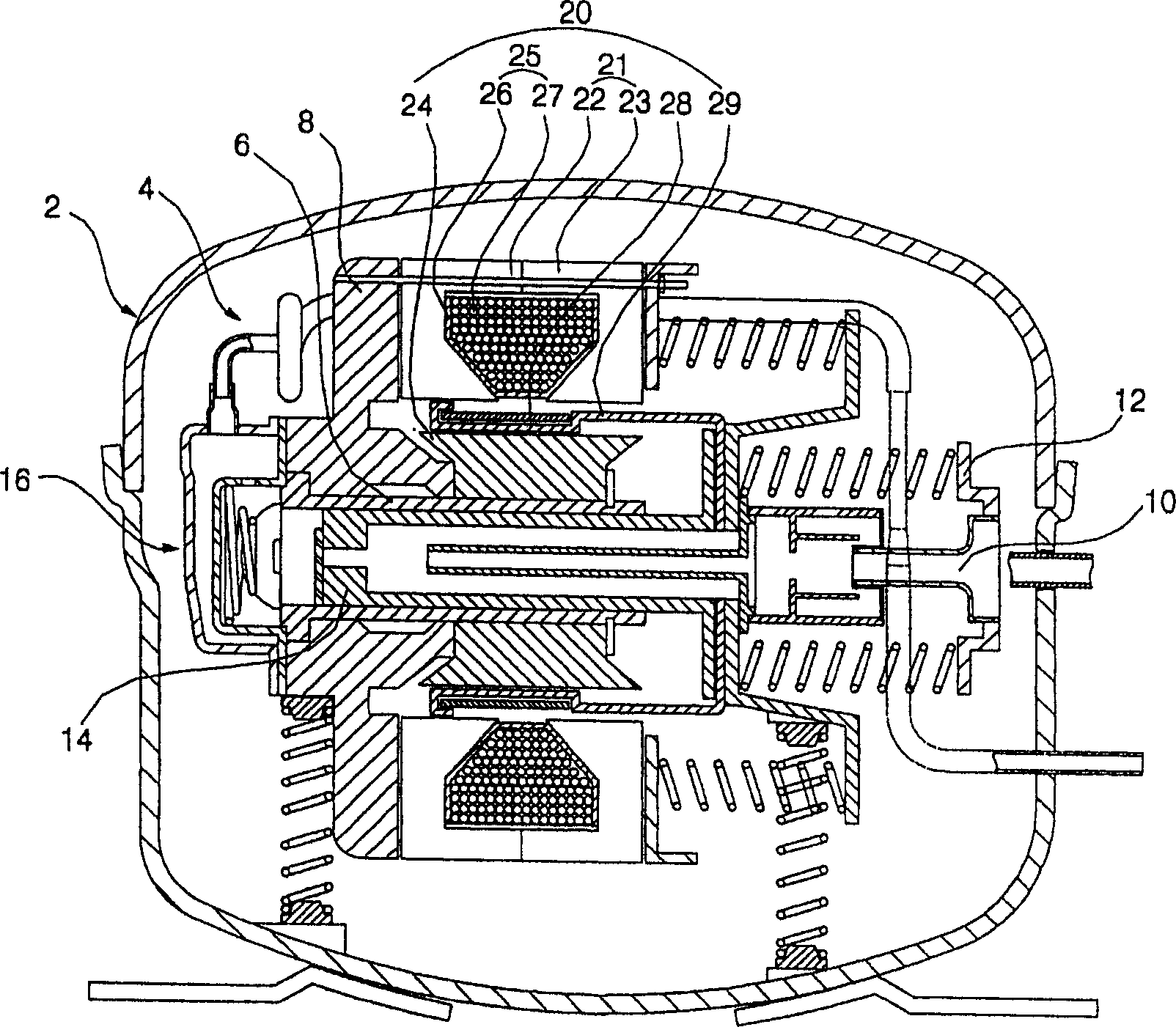
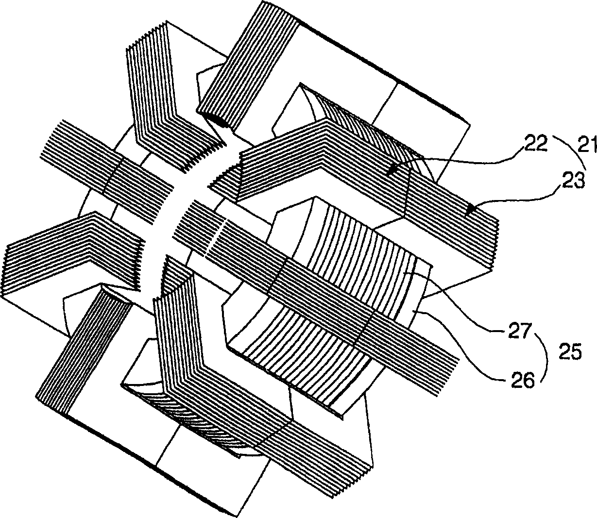
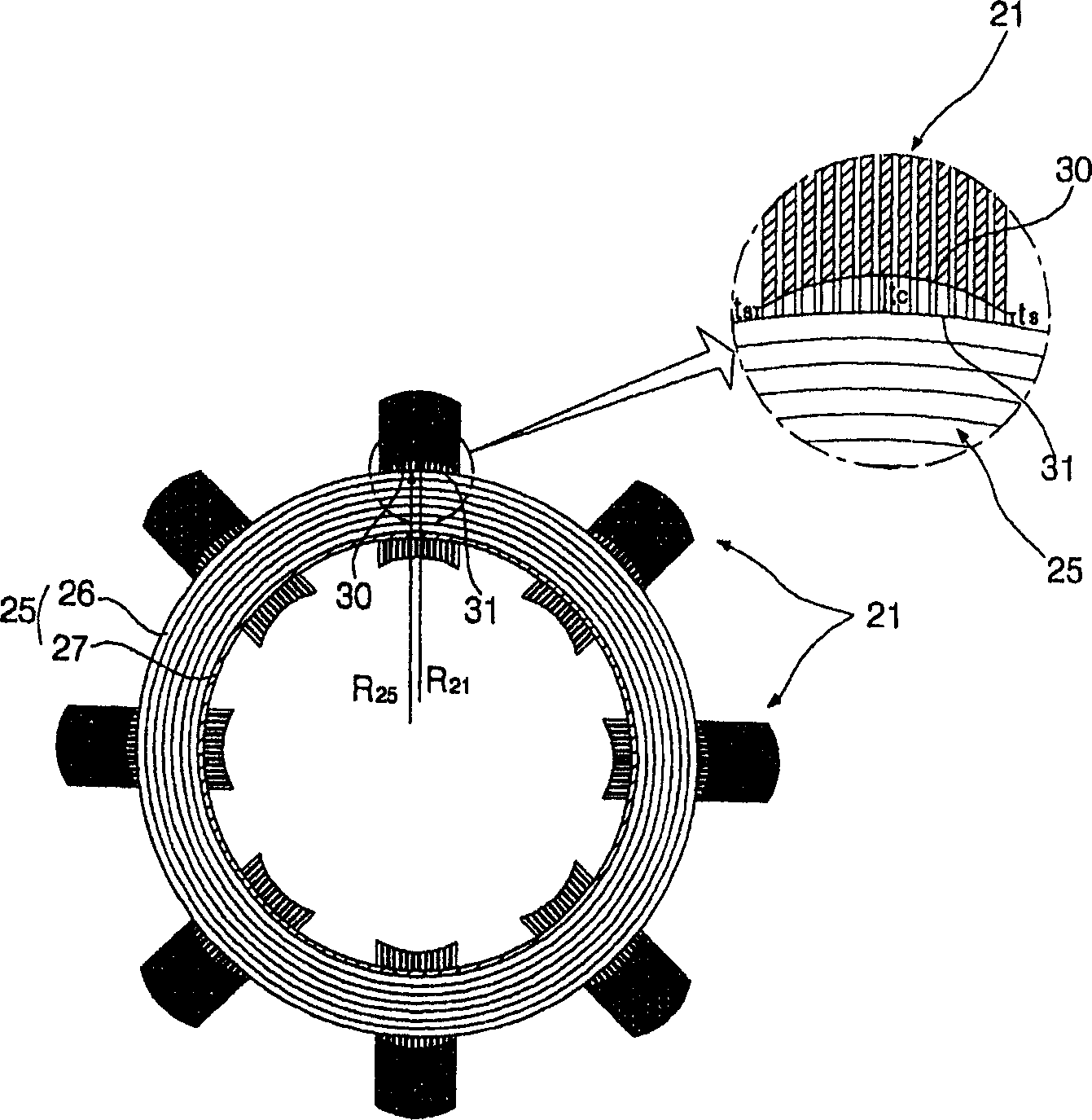
[0050] Figure 5 A longitudinal sectional view showing a linear compressor in which a linear motor according to a first preferred embodiment of the present invention is installed, Figure 6 shows a perspective view of a stator of a linear motor according to a first preferred embodiment of the present invention, Figure 7 yes Figure 6 A cross-sectional view of a linear motor stator according to a first preferred embodiment of the present invention shown in, Figure 8 yes Figure 6 A longitudinal sectional view of a linear motor stator according to a first preferred embodiment of the present invention shown in, Figure 9 A perspective view of an outer core block constituting a stator of a linear motor according to a first preferred embodiment of the present invention is shown.

[0051] see Figure 5 , the linear compressor in which the linear m...


PUM


Abstract

In a stator of a linear motor having a plurality of outer core blocks, each of the outer core blocks comprises first and second side core blocks and a center core block. The center core block has an inner diameter equal to an outer diameter of a coil block. Consequently, insulation and heat transfer efficiencies are improved, and the size of the linear motor is minimized. Furthermore, the center core block is provided with a heat sink part, which is inserted in a coil block for dissipating heat from the coil block. Consequently, heat generated from the coil block is effectively dissipated.

Description

technical field [0001] The present invention relates to a linear motor, and more particularly, to a stator for a linear motor having a plurality of outer cores, wherein each outer core includes first and second side cores and a middle core, and the The inner diameter of the intermediate core block is equal to the outer diameter of the coil assembly, thus improving insulation and heat transfer efficiency and minimizing the volume of the linear motor. Background technique [0002] Generally, a linear compressor is a device that sucks, compresses, and discharges refrigerant gas (hereinafter referred to as "fluid") through the linear reciprocating motion of a piston in a cylinder, which is driven by a linear driving force of a linear motor. implemented. [0003] figure 1 A longitudinal sectional view showing a linear compressor with a conventional linear motor installed therein, figure 2 is a perspective view showing a stator of a conventional linear motor, image 3 yes f...

Claims


Application Information

Patent Timeline
Patent Type & Authority Applications(China)
IPC IPC(8): H02K33/18
CPCH02K1/16H02K1/32H02K3/34H02K33/16H02K41/02
Inventor 崔善镕郑相燮李爀
Owner LG ELECTRONICS INC
Learn More