Fuel gas calorie control equipment and gas turbine system
A technology for controlling equipment and calories. It is used in turbine/propulsion fuel delivery systems, gas turbine units, and fuel control of turbine/propulsion units. It can solve problems such as large delays, poor response of gas calorimeters, and rapid fluctuations in gas calories. , to achieve the effect of stable combustion state, stable volatility, and suppression of volatility
- Summary
- Abstract
- Description
- Claims
- Application Information
AI Technical Summary
Problems solved by technology
Method used
Image
Examples
no. 2 example
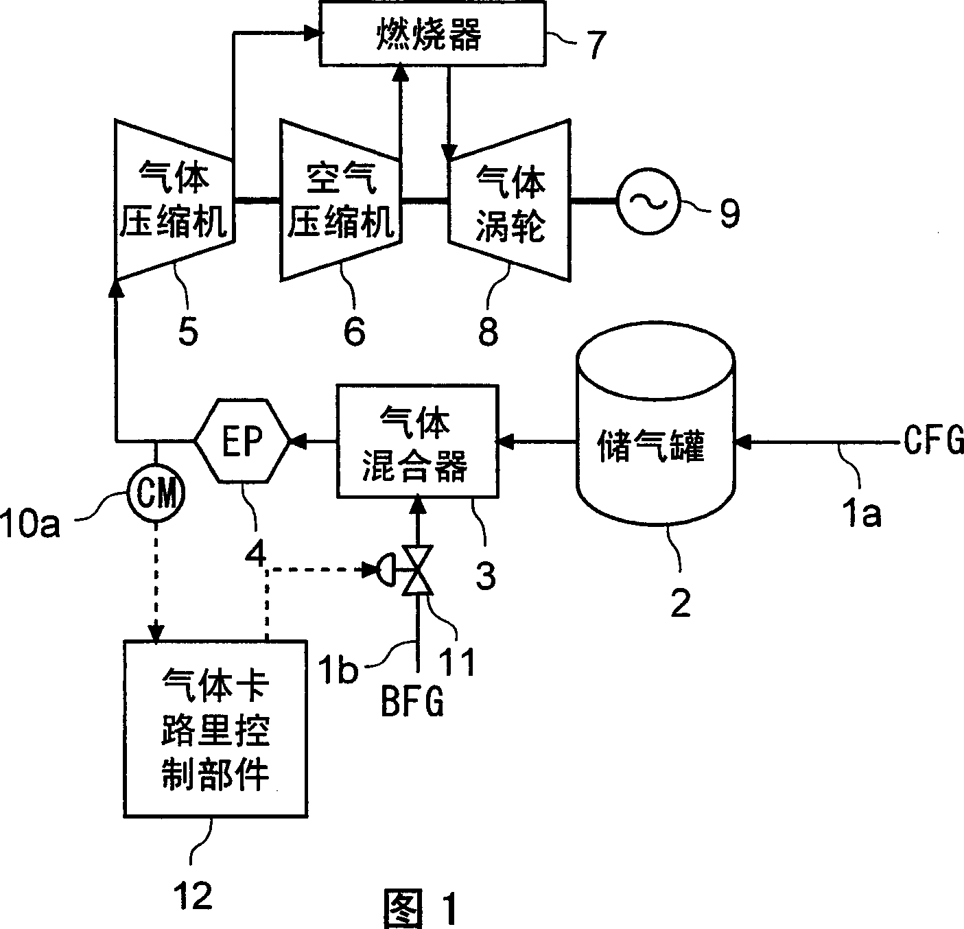
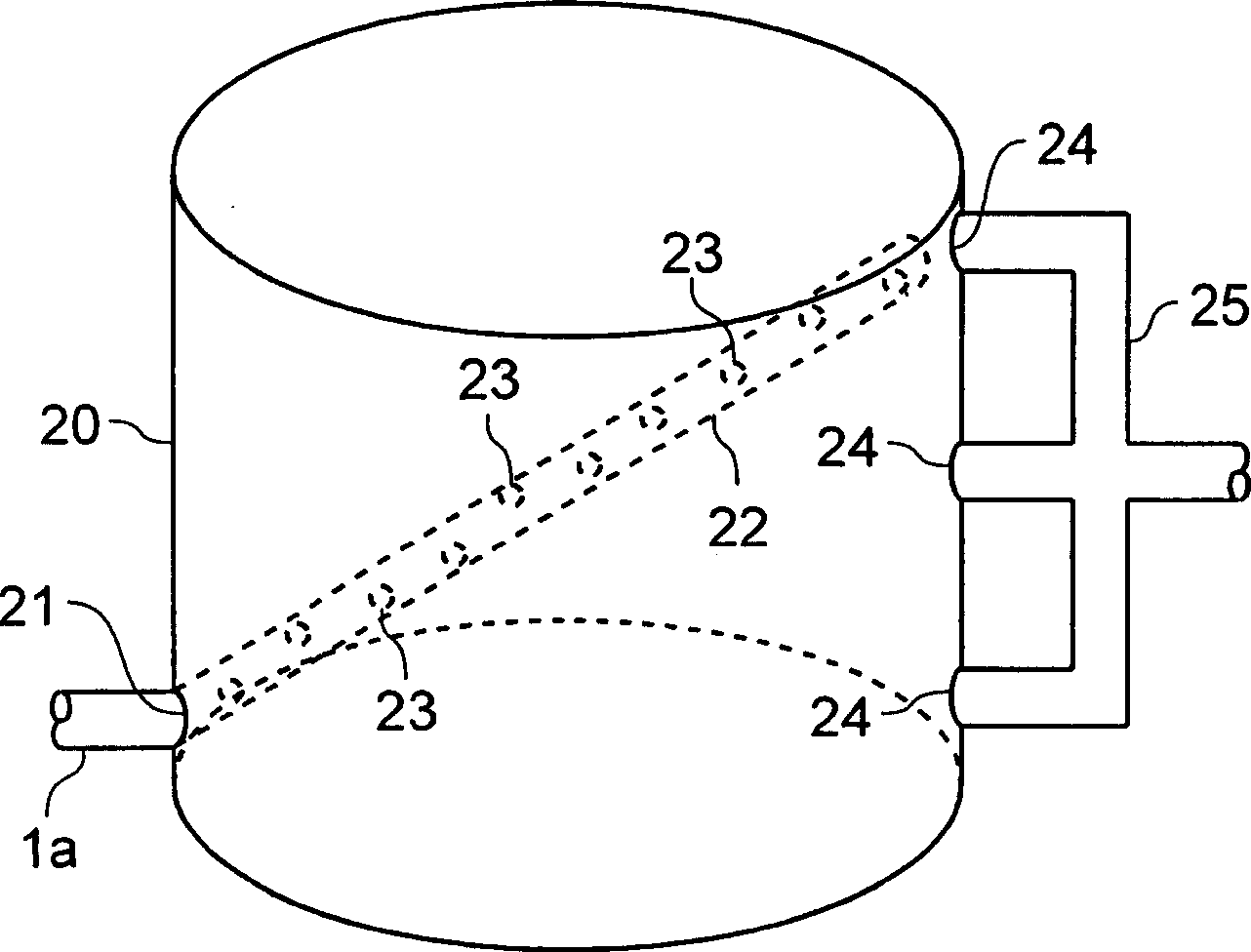
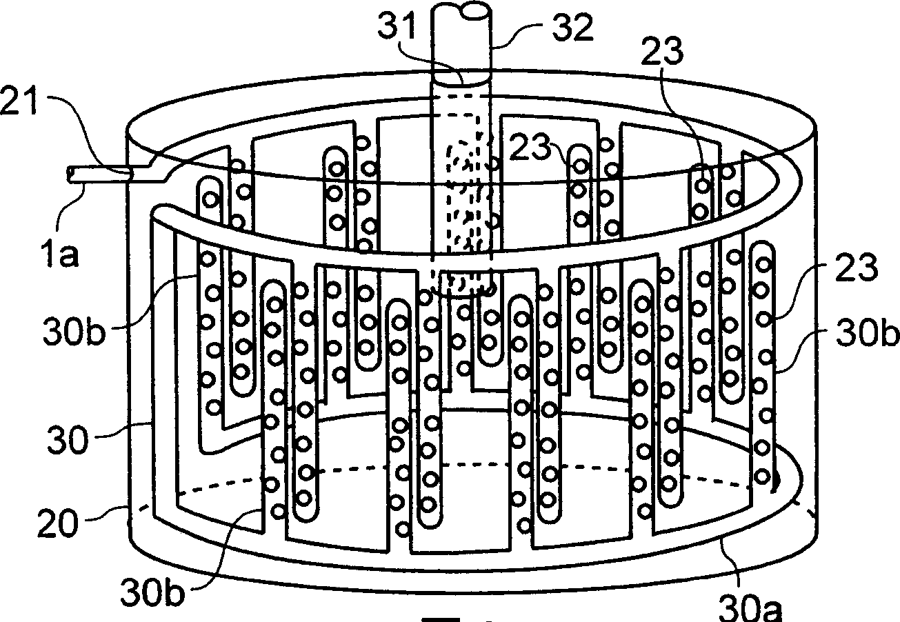
[0083] A second embodiment of the present invention will be described with reference to the accompanying drawings. Figure 10 is a structural block diagram showing the gas turbine system according to the present embodiment. exist Figure 10 In the structure shown in , parts that are the same as those in FIG. 1 will have the same reference numerals, and their detailed description will be omitted. Furthermore, as in the first to eighth configuration examples according to the first embodiment (see figure 2 The gas storage tank of the configuration shown in FIG. 9 ) will be used for the gas storage tank in the gas turbine system according to the present embodiment, and its detailed description will be omitted.
[0084] Figure 10 The gas turbine system in is the gas turbine system according to the first embodiment (see FIG. 1 ), which adds: a gas calorimeter 10b for measuring the gas calorie of CFG discharged after the delay effect is provided in the gas storage tank 2 and ins...
no. 3 example
[0089] A third embodiment of the present invention will be described with reference to the accompanying drawings. Figure 11 is a structural block diagram of the gas turbine system according to the current embodiment. exist Figure 11 In the structure, with Figure 10 Parts with the same structure will have the same reference numerals, and their detailed descriptions will be omitted. Furthermore, as in the first to eighth configuration examples according to the first embodiment (see figure 2 The gas storage tank of the configuration shown in FIG. 9 ) will be used for the gas storage tank in the gas turbine system according to the second embodiment, and its detailed description will be omitted.
[0090] Figure 11 The gas turbine system in is according to the second embodiment (see Figure 10 ) gas turbine system, which has increased: a gas calorimeter 10c for measuring the gas calorie of CFG passing through the CFG inlet pipe 1a before being supplied to the gas storage ta...
PUM
 Abstract
Description
Claims
Application Information
 - R&D
- Intellectual Property
- Life Sciences
- Materials
- Tech Scout
- Unparalleled Data Quality
- Higher Quality Content
- 60% Fewer Hallucinations
Browse by: Latest US Patents, China's latest patents, Technical Efficacy Thesaurus, Application Domain, Technology Topic, Popular Technical Reports.
© 2025 PatSnap. All rights reserved.Legal|Privacy policy|Modern Slavery Act Transparency Statement|Sitemap|About US| Contact US: help@patsnap.com


