
Hole-forming method and device based on laser shock wave technology

A technology of shock wave and laser pulse, which is applied in the field of rapid prototyping of holes, can solve the problems of slag hanging in the incision, large diffusion effect, poor production environment, etc., and achieve the effect of avoiding particles and dust, wide range of materials, and clean environment

Inactive Publication Date: 2006-09-06
JIANGSU UNIV
View PDF1 Cites 28 Cited by
  • Summary
  • Abstract
  • Description
  • Claims
  • Application Information

AI Technical Summary

Problems solved by technology

The most commonly used cutting tool is CO 2 Although the laser has the advantages of high efficiency and convenient operation, it has the following disadvantages: there are periodic ripples on the incision section, which seriously affects the surface quality of the orifice; due to thermal effects, there are often microcracks on the surface of the plate, and dross appears below the incision phenomenon; due to the auxiliary gas used, the molten material splashes, and the production environment is poor, which cannot meet the processing of high-cleanliness parts; the range of material processing is limited to a certain extent, and the processing of some materials such as copper and aluminum alloys becomes Difficult to obtain, and may even damage the external optics of the laser system
[0007] The technology closest to the technology of the present invention is explosive punching. Explosive forming mainly uses the instantaneous high temperature and high pressure shock wave punching produced when explosives explode, but the process parameters of explosive punching are difficult to control, and the shock wave action time is as long as several years. Milliseconds, the diffusion effect is large, the shape of the hole cannot be precisely formed, and the safety is poor, so it is not used

Method used


Image

  • Hole-forming method and device based on laser shock wave technology
  • Hole-forming method and device based on laser shock wave technology
  • Hole-forming method and device based on laser shock wave technology

Examples


Embodiment Construction

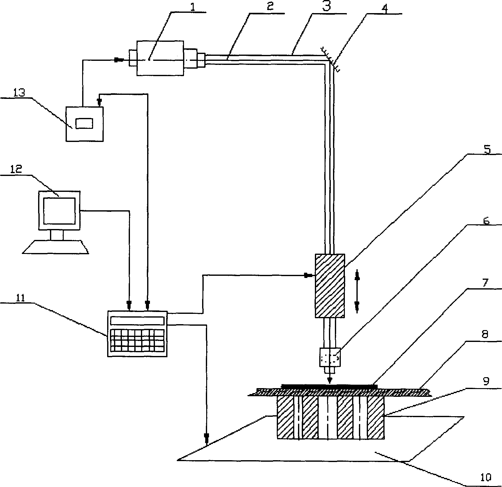
[0030] The laser generator (1) generates a laser pulse beam (2) with an energy of 10-100 joules and a duration of 8-80 nanoseconds, with a power density greater than GW / cm 2 , after the spot mode can be basic mode, multi-mode and other modes, it passes through the light guide wall (3) and the total reflection environment (4) to the spot size adjustment device (5), and adjusts the focusing device (6). The adjustment device (5) can adjust the distance between the focusing device and the plate to obtain the required spot diameter, and then the laser is irradiated on the transparent confinement layer and the energy absorption coating of the energy conversion body on the surface of the plate, and the confinement layer confines the plasma Expansion, increasing the pressure of the plasma blaster. After the energy-absorbing coating absorbs the high-energy laser, it rapidly vaporizes and ionizes to form plasma, and the plasma continues to absorb the laser energy to form a detonation wa...


PUM

PropertyMeasurementUnit
Thicknessaaaaaaaaaa
Thicknessaaaaaaaaaa

Abstract

The invention relates to a hole molding method based on laser impact wave technique and relative device. Plating energy-adsorption layers and transparent restrain layers on the positions that needing holes, while the areas of them are larger than the processing hole; according to the shape and size of processing hole, preparing concave, and arranging the work-piece on the concave mold to make the centers of energy-adsorption layer, transparent restrain layer, the processed hole and concave mold matched; arranging the concave mold on the multiple-axle linkage workbench; according to the size of hole, setting the light spot size and the energy of laser impulse; the laser beam via the light guide tube, reflective glass, light spot adjuster, focusing device and transparent restrain layer is emitted on the energy-adsorption layer to induce the laser impact wave, which can compress the work-piece, to complete the punch. The invention has the advantages that: larger processing radius, and lower processing cost.

Description

technical field [0001] The present invention mainly relates to the field of laser processing, in particular to a method and device for rapid forming of holes based on laser shock wave technology, and is especially suitable for round holes, square holes, triangular holes and other holes formed on metal plates with a thickness of less than 2.5mm. Regular shaped holes. Background technique [0002] Metal sheet processing has occupied a very important position in the entire national economy, and is widely used in aerospace, shipbuilding, automobile coverings, home appliances and other production industries. Due to the needs of the structure, there are often many round holes and irregular shapes on the metal sheet The common processing methods mainly include drilling, die punching, laser drilling and laser cutting hole forming. [0003] Drilling is currently a widely used forming method for medium and thick plates. However, due to the extremely low rigidity of thin plates, high ...

Claims


Application Information

Patent Timeline
IPC IPC(8): B23K26/38B23K26/18B23K26/04B23K26/06B23K26/42B21D28/26
CPCB23K26/0069B23K26/356
Inventor 周建忠张兴权张永康顾永玉杨超君倪敏雄
Owner JIANGSU UNIV
Learn More