
Electric connector

A technology for electrical connectors and connecting grooves, which is applied in the direction of connecting parts to protect grounding/shielding devices, etc., and can solve the problems of insufficient strength, loss of aesthetic feeling, and increased volume of buckle shrapnel 21

Inactive Publication Date: 2006-08-02
TOP YANG TECH ENTERPRISE CO LTD
View PDF0 Cites 3 Cited by
  • Summary
  • Abstract
  • Description
  • Claims
  • Application Information

AI Technical Summary

Problems solved by technology

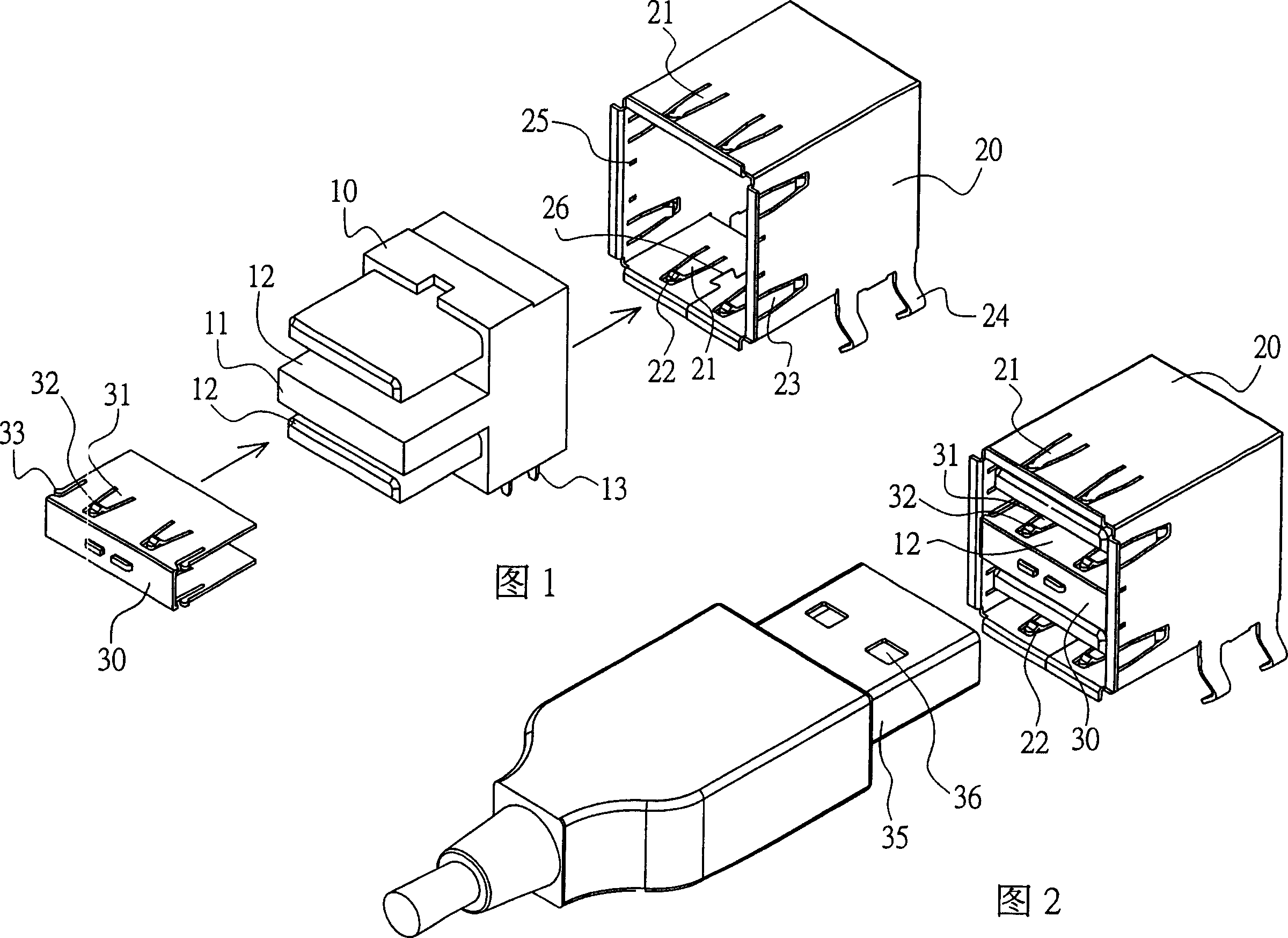
[0005] 1. Since the upper and lower surfaces of the metal shell 20 are respectively stamped with two buckle springs 21 for buckling the holes 36 of the USB connector 35, in order to achieve a stable buckle effect, the buckle springs 21 need to have appropriate Only the strength can achieve a stable buckle, so the metal shell 20 cannot use a thinner plate, otherwise the strength of the buckle shrapnel 21 will not be enough, so the effect of saving materials cannot be achieved
[0006] 2. Since two buckle springs 21 and two grounding springs 23 are directly punched out on the plate surface of the metal shell 20, if made of metal with poor elasticity, the buckle springs 21 and grounding springs 23 will not be flexible enough to be used
[0007] 3. The metal casing 20 is formed by bending a metal plate cut with five plates, and the plate body after unfolding is irregular, so a lot of waste is bound to be produced in the manufacture, and also due to the irregularity of the plate body Regular shape will increase the volume, so it will increase the cost of electroplating
[0008] 4. The upper and lower surfaces of the metal shell 20 are stamped with two buckle springs 21 and two grounding springs 23 respectively, forming punching marks, and there will also be folded seam lines 26, which will lose the aesthetic feeling of the overall appearance and cover the effect Poor will affect the anti-electromagnetic interference effect

Method used


Image

  • Electric connector
  • Electric connector
  • Electric connector

Examples


Embodiment Construction

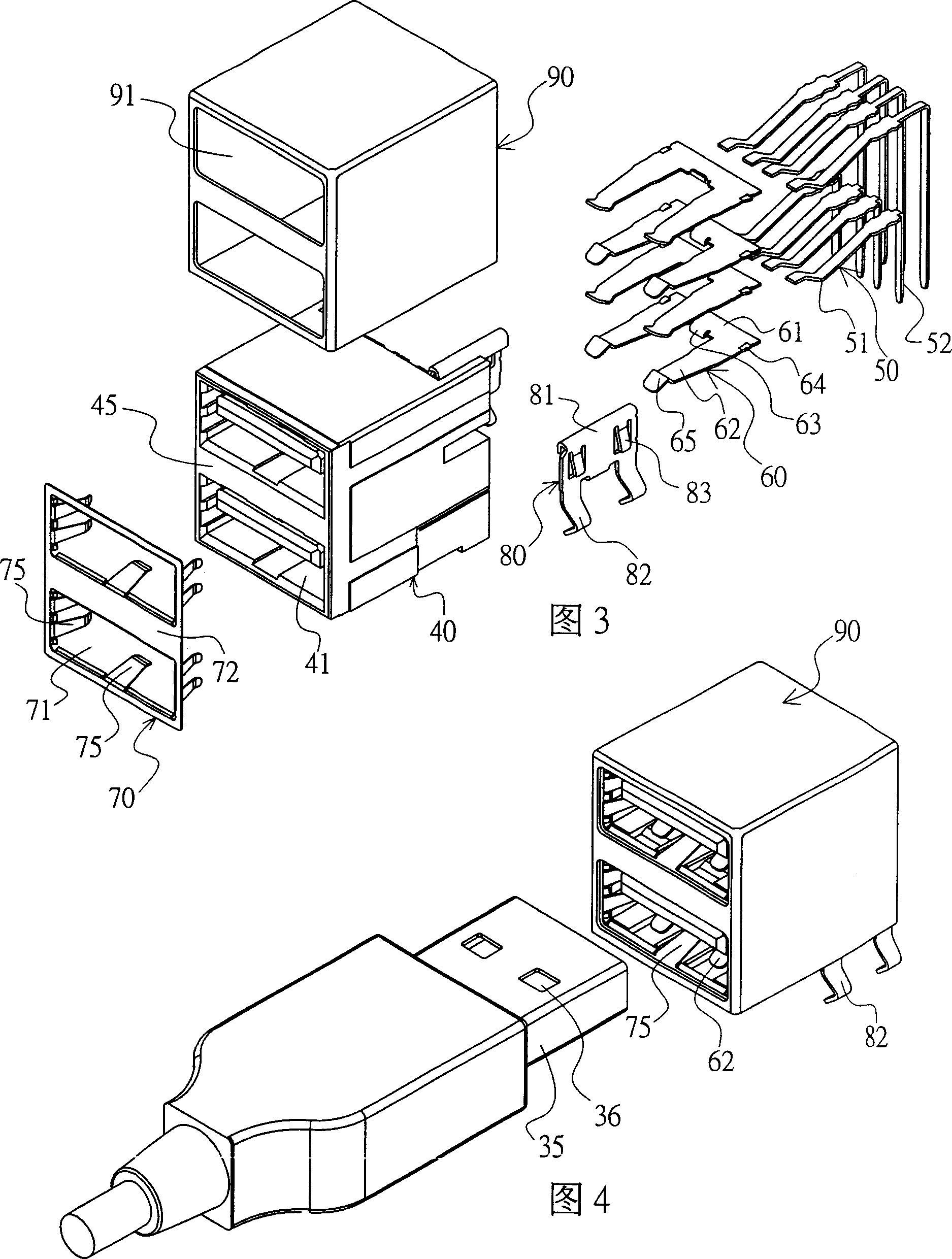
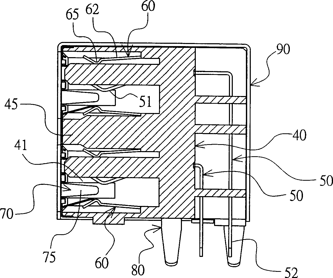
[0051] Please refer to Figure 3, Figure 4 and Figure 5 , is the first embodiment of the present invention, which is a double-layer USB electrical connector, which is used to electrically connect a USB connector 35, and the USB connector 35 is provided with at least one card hole 36, which includes: a plastic Base body 40, four buckle elements 60, a grounding element 70, two clamp elements 80, and a metal shell 90, wherein:

[0052] The plastic seat body 40 is provided with at least two connecting grooves 41 and a plurality of terminals 50. The front end of the connecting groove 41 is an insertion port for the USB connector 35. Please refer to Image 6 As shown in Fig. 7, two socket slots 42 and a stop surface 43 are respectively provided behind each connecting groove 41, a partition 45 is arranged between the two connecting grooves 41, and each terminal 50 is provided with a contact portion 51 located in the connecting groove 41 and a pin portion 52 extend to the lower end of...


PUM


Abstract

This invention provides a kind of electric connector. It concludes: a plastic stand, on which is arranged with a connecting slot and many terminals. Each terminal is arranged with a pin part which extends out of the plastic stand; a metal shell which uses aluminium to machining integrative shaping by extruding. It forms an outer casing without joints, which coats the plastic stand; at least a clip component which sets a fixing part and at least a clip spring sheet. It is assembled and fixed in the plastic stand through the fixing part. The clip spring sheet is positioned in the connecting slot of plastic stand. There is a protuberant clip part close to the end. The clip part is used to clip a clamping hole of transmission line joint; at least a ground connecting component which is arranged with a locating part and at least a ground connecting spring sheet. It is located at the plastic stand through the locating part and connected with metal shell. Each ground connecting spring sheet is in the connecting slot.

Description

technical field [0001] The invention relates to an electrical connector, in particular to an electrical connector with a metal shell. Background technique [0002] Please refer to Fig. 1 and Fig. 2, it is a kind of conventional double-layer USB electrical connector connected to universal serial bus (referred to as USB) connector, which includes a plastic seat body 10, and its front end is provided with a partition 11 and two connectors Groove 12 is provided with a plurality of terminals 13 in it; a metal shell 20 is sleeved and coated on the plastic seat body 10, so that the connection groove 12 of the plastic seat body and the pin portion of each terminal 13 are connected with the outside world Connected, the upper and lower plates are divided into two stamping springs 21, and the buckle springs 21 are provided with a protruding buckle part 22 near the end, and two grounding springs 23 are stamped on the two side plates respectively. Both sides of the lower end are provide...

Claims


Application Information

Patent Timeline
IPC IPC(8): H01R13/648H01R13/652
Inventor 蔡周旋
Owner TOP YANG TECH ENTERPRISE CO LTD
Learn More