
Thumb mechanism of underactuated self-adaptive hand prosthesis

An underactuated, self-adaptive technology applied in the field of anthropomorphic manipulators

Inactive Publication Date: 2006-07-19
HARBIN INST OF TECH
View PDF0 Cites 46 Cited by
  • Summary
  • Abstract
  • Description
  • Claims
  • Application Information

AI Technical Summary

Problems solved by technology

[0003] The purpose of the present invention is to solve the problem that the thumbs of most existing prosthetic hands only have one direction of grasping movement, and provide a thumb mechanism for an underactuated self-adaptive prosthetic hand

Method used


Image

  • Thumb mechanism of underactuated self-adaptive hand prosthesis
  • Thumb mechanism of underactuated self-adaptive hand prosthesis
  • Thumb mechanism of underactuated self-adaptive hand prosthesis

Examples


specific Embodiment approach 1

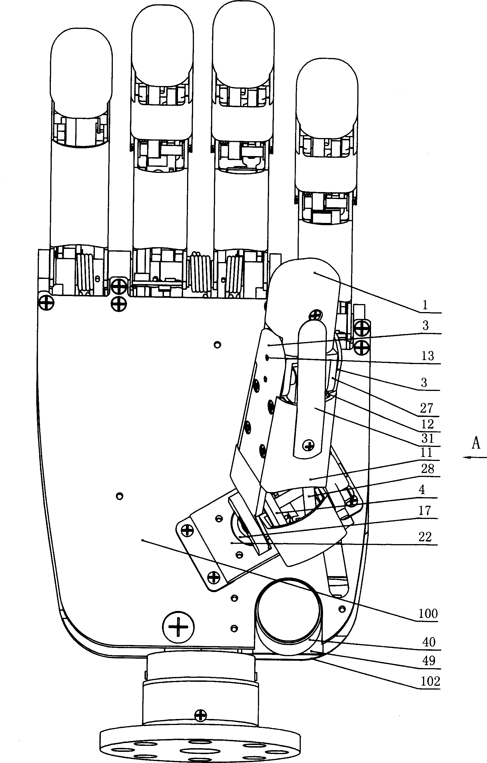
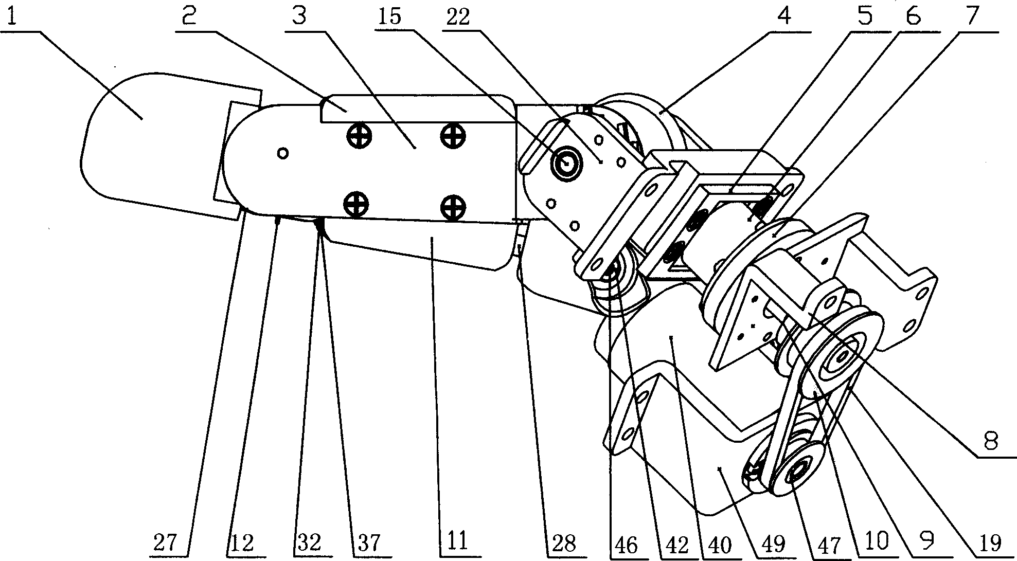
[0005] Specific embodiment one: (see Figure 1~Figure 8 ) This embodiment consists of an under-driving mechanism of the thumb and a transmission mechanism of the thumb. The under-driving mechanism of the thumb consists of a thumb fingertip sleeve 1, a lower thumb cover 2, a right thumb plate 3, a thumb upper cover 11, and a fingertip spring. 12. Thumb fingertip shaft 13, torque sensor 20, fingertip 27, thumb link 28, thumb left plate 30, thumb fingertip pin sleeve 32, thumb link pin 33, thumb fingertip link pin 37, The thumb spring stop pin 38, the ball hinge 42, and the ball hinge connecting rod pin 46 are composed. The thumb fingertip shaft 13 is set at the upper end between the thumb right plate 3 and the thumb left plate 30, and the lower end of the fingertip 27 is set on the thumb On the fingertip shaft 13, the thumb fingertip sleeve 1 is fixed on the fingertip 27, the thumb spring stop pin 38 is fixed on the inner upper end of the right thumb plate 3, the fingertip spring 12 ...

specific Embodiment approach 2

[0006] Specific implementation manner two: (see figure 1 , Picture 9 ) This embodiment is different from the first embodiment in that it adds a thumb elastic cover 31, one end of the thumb elastic cover 31 is fixed on the outer surface of the thumb upper cover 11, and the other end of the thumb elastic cover 31 It is frictionally connected with the outer surface of the thumb fingertip sleeve 1. The other composition and connection relationship are the same as in the first embodiment. The function of the added thumb elastic cover plate 31 is to protect the transmission mechanism inside the thumb from being exposed, prevent foreign objects from entering, and affect the service life.

[0007] Working principle: the output shaft of the motor 40 drives the thumb motor pulley 48 to rotate, drives the thumb reducer pulley 10 to rotate, the thumb reducer pulley 10 drives the wave generator shaft 54 ​​to rotate, and the wave generator shaft 54 ​​drives the harmonic gear reducer The wave ...


PUM


Abstract

The invention discloses a thumb device of little-driving self-adaptive artificial hand, which is characterized by the following: connecting one end of thumb finger-tip pin case (32) with the thumb finger-tip connecting rod pin shaft (37); fixing the thumb wheeled bearing (55) on the wave generator axle (54) under the thumb decelerator wheel (10); connecting the thumb decelerator wheel (10) with the wheeled pad (9) through the wheeled fixation pin (57); fixing the wave generator (52) of harmonic gear decelerator on the other end of the wave generator axle (54) of wheeled pad (9). The invention can display a 130 deg conical moving space in the moving course to realize the finger-pin little-driving movement, which is adaptive for the object shape to reach full-covering the object and stable grasping.

Description

Technical field [0001] The invention relates to an anthropomorphic robot hand. Background technique [0002] Most existing prosthetic hand thumbs only have one direction of gripping movement. Such a thumb must be set perpendicular to the palm of the prosthetic hand. Both in appearance and function, it is very different from the thumb of a real human hand. It is also for this reason that many disabled people who need to install prosthetic hands are unwilling to use prosthetic hands. According to surveys, more than half of disabled people pay more attention to the realistic appearance of prosthetic hands than to their functions. It can be said that this is a big bottleneck in the current design of prosthetic hands. Contents of the invention [0003] The purpose of the present invention is to provide an under-actuated adaptive prosthetic hand thumb mechanism to solve the problem that most existing prosthetic hand thumbs have only one direction of grasping movement. The inve...

Claims


Application Information

Patent Timeline
Patent Type & Authority Applications(China)
IPC IPC(8): B25J15/08
CPCB25J15/0009
Inventor 刘宏姜力黄海侯琳琪
Owner HARBIN INST OF TECH
Learn More