477-566MHZ micropower wireless remote control transmitting, receiving circuit

A micro-power wireless and transmitting circuit technology, applied in the field of wireless remote control, can solve the problems of motor spark interference and poor load characteristics, and achieve the effect of overcoming the influence of frequency and strong anti-interference.

Inactive Publication Date: 2006-05-03
SHANGHAI DILAIBANG ELECTRONICS TECH
View PDF0 Cites 3 Cited by
  • Summary
  • Abstract
  • Description
  • Claims
  • Application Information

AI Technical Summary

Problems solved by technology

[0005] The technical problem to be solved by the present invention is to provide a 477-566MHZ micro-power wireless remote control transmitting and receiving circuit, which aims to solve the defects of motor spark interference and poor load characteristics in the prior art

Method used


Image

  • 477-566MHZ micropower wireless remote control transmitting, receiving circuit
  • 477-566MHZ micropower wireless remote control transmitting, receiving circuit
  • 477-566MHZ micropower wireless remote control transmitting, receiving circuit

Examples


Embodiment Construction

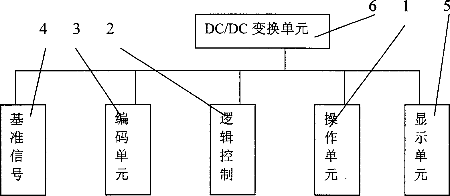
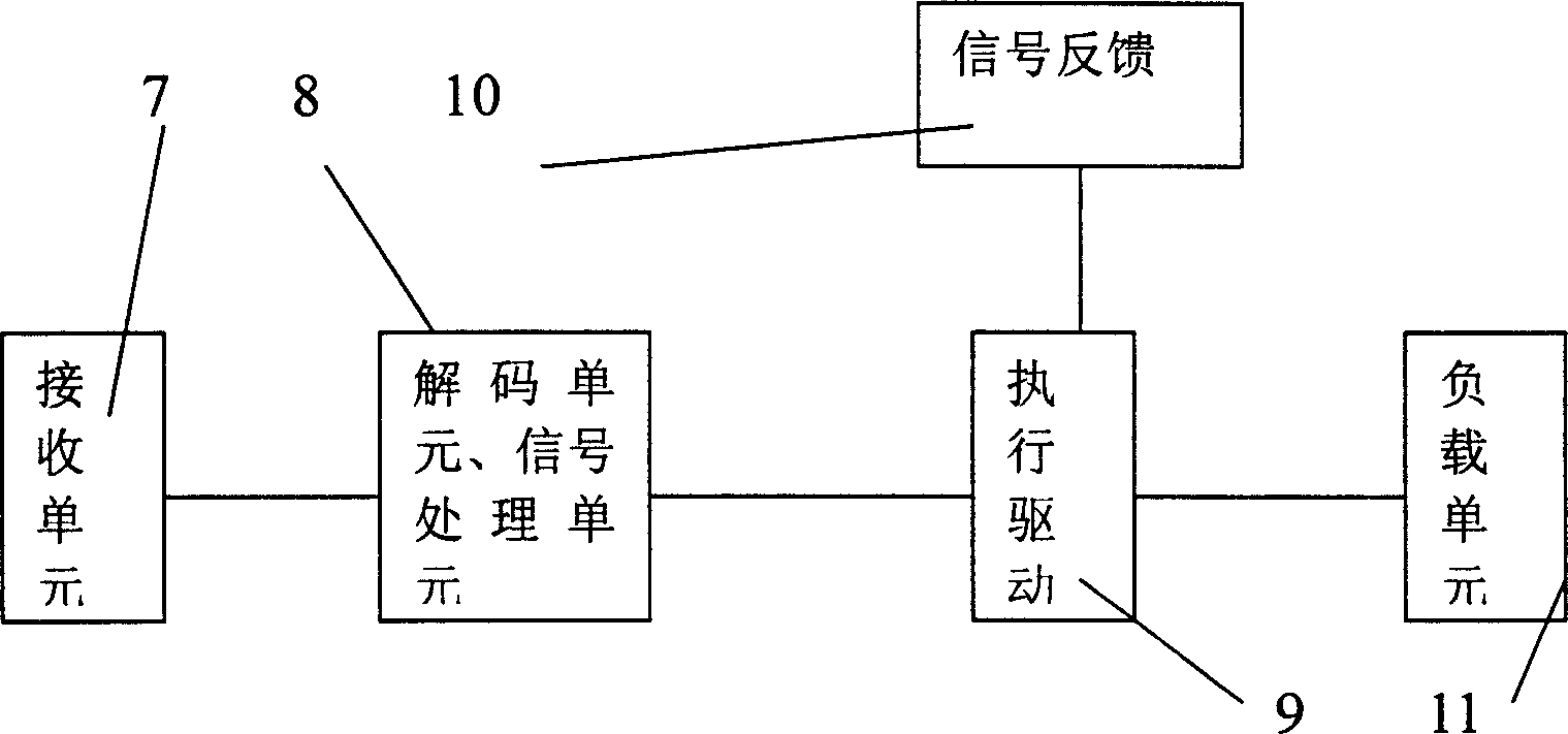
[0015] Below in conjunction with accompanying drawing and specific embodiment the present invention is described in further detail:

[0016] Depend on figure 1 , figure 2 It can be seen that the micro-power wireless remote control transmission circuit of the present invention includes: an operating unit 1 for sending on and off signals; a logic control unit 2 for logically processing the control signals sent by the operating unit, without causing false control , out of control; a coding unit 3, with 12-bit tri-state address pins, used to support up to 531441 (or 3 12 ) codes of addresses can greatly reduce code conflicts and illegally scan the codes so that the possibility of matching has strong anti-interference; a reference signal unit 4 uses a surface acoustic wave (SAW) frequency that is very stable, Reliable 477-566MHZ high-frequency signal, which is less affected by temperature and load impedance changes, is used for non-directional transmission. This frequency band m...


PUM


Abstract

The invention relates to a 477-566MHZ micro power wireless remote control transmitting and receiving circuit which comprises: an operating unit (1), a logic control unit (2), a encoding unit (3), a reference signal unit (4), a display unit (5) which adopts light-emitting diode or liquid crystal display mode to finish and is used to display the transmitter cell and the carrying condition of the operating condition, a DC/DC converting unit (6) which is connected with the operating unit (1), the display unit (5), the logic control unit (2), the encoding unit (3) and the reference signal unit (4), wherein the receiving circuit comprises a receiving unit (7), a decoding unit, a signal processing unit (8), an executing driven unit (9), a signal feedback unit (10), and a loading unit (11).

Description

technical field [0001] The invention relates to the field of wireless remote control, in particular to a micropower wireless remote control transmitting and receiving circuit with a bandwidth of 477-566MHZ. Background technique [0002] In the field of micro-power wireless remote control, the interference of motor sparks will affect the receiving frequency; it is more likely to cause a drop in voltage after a heavy load, resulting in weakening of the output signal, narrowing of the frequency band, and unstable receiving performance, which will cause the breaker of the drive part to be generated. shake. [0003] At present, in order to overcome the above-mentioned defects, technicians use JI filter, magnetic ring, inductance and other methods to resist interference, but the effect is not ideal, and the price is expensive; the characteristics are not satisfactory under heavy load, and the remote control distance is greatly shortened. To the practical stage; some even solve it...

Claims


Application Information

Patent Timeline
Patent Type & Authority Applications(China)
IPC IPC(8): G08C17/02
Inventor 史新国田宗保魏永强史新元
Owner SHANGHAI DILAIBANG ELECTRONICS TECH
Why Eureka
Try Eureka