Eureka AIR delivers breakthrough ideas for toughest innovation challenges, trusted by R&D personnel around the world.

Apparatus for purifying exhaust gas

A catalyst, turbocharger technology, applied in the direction of exhaust device, muffler device, charging system, etc.

Inactive Publication Date: 2006-04-05
TOYOTA JIDOSHA KK
View PDF0 Cites 8 Cited by
  • Summary
  • Abstract
  • Description
  • Claims
  • Application Information

AI Technical Summary

Problems solved by technology

Therefore, problems can arise related to the limited interior panel space in the vehicle
In addition, even when the oxidation catalyst is set in this way, there is a problem that not only the liquid reducing agent but also PM has adhered to the surface of the inlet end of the oxidation catalyst

Method used


Image

  • Apparatus for purifying exhaust gas
  • Apparatus for purifying exhaust gas
  • Apparatus for purifying exhaust gas

Examples


example 1

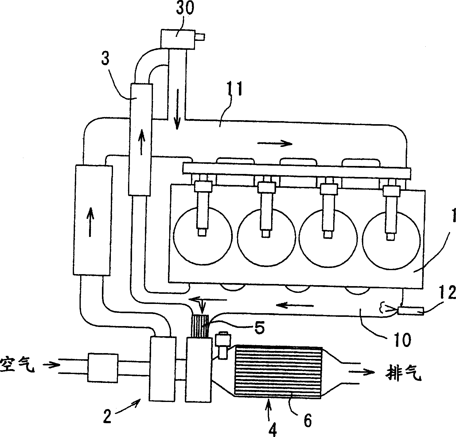
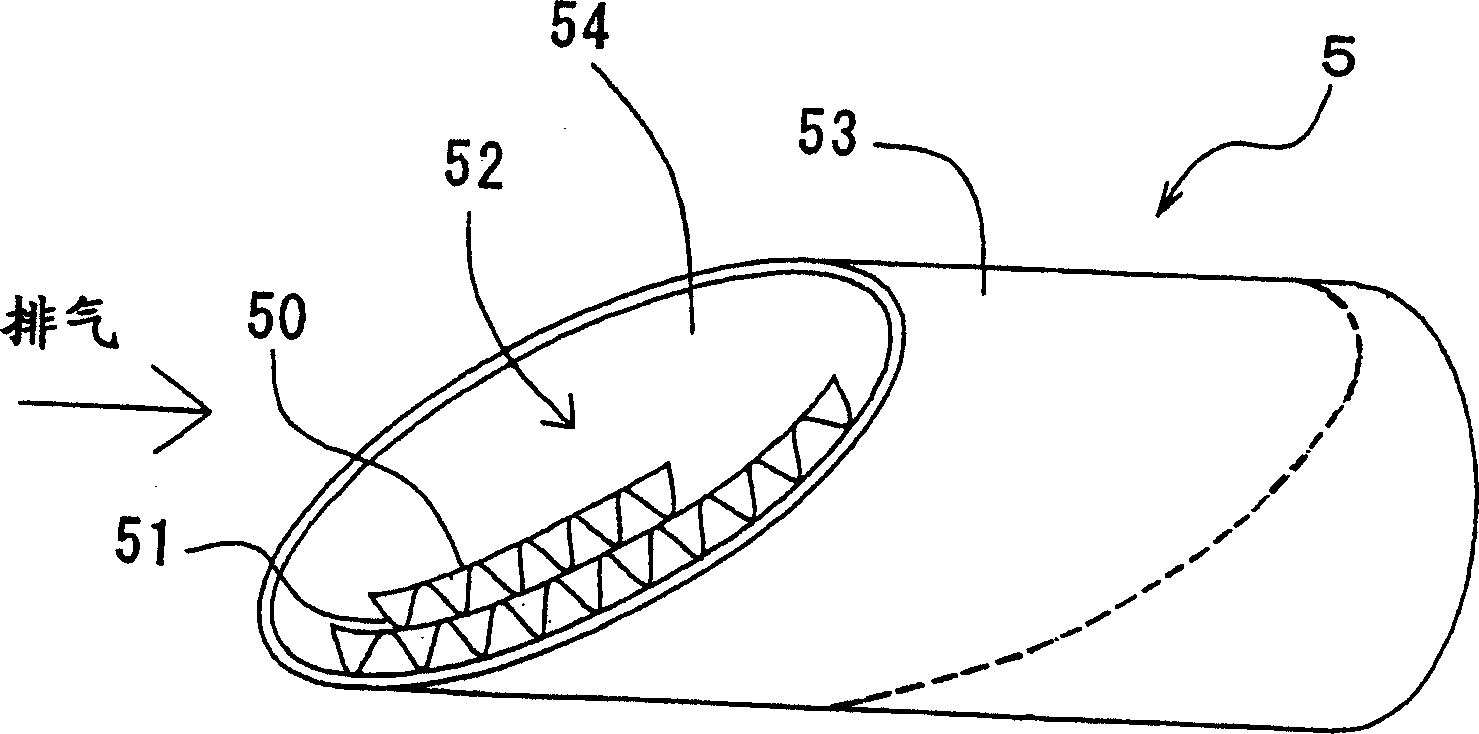
[0044] figure 1 An exhaust purification device according to Example 1 of the present invention is shown. The exhaust system of the direct injection diesel engine 1 is branched from the exhaust manifold 10 into two flow paths. A turbocharger 2 is provided in one of the flow passages, and an exhaust gas circulation (hereinafter abbreviated as "EGR") cooler 3 is provided in the other flow passage. Exhaust gas discharged from the turbocharger 2 passes through the catalytic converter 4 and is discharged to the outside. On the other hand, the exhaust gas passing through the EGR cooler 3 is returned to the intake manifold 11 , and the flow rate is controlled by the EGR valve 30 . An injector 12 is installed on the upstream side of the exhaust gas flow with respect to the turbocharger 2 in order to add light oil to the exhaust gas. A small honeycomb oxidation catalyst 5 is disposed between the injector 12 and the turbocharger 2 . In addition, the catalytic converter 4 is equipped ...

example 2

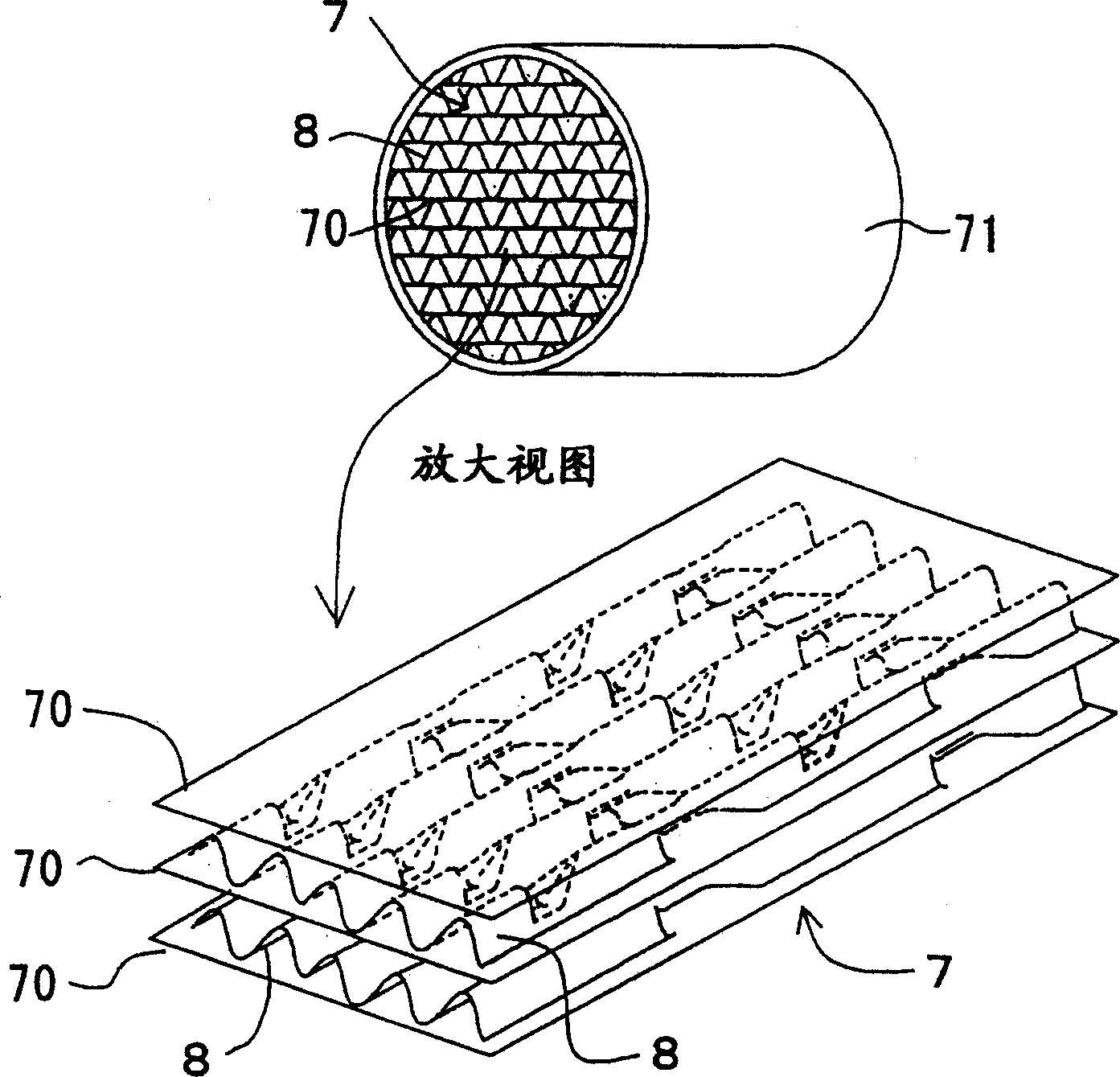
[0050] In addition to setting image 3 The arrangement of the exhaust gas purification device according to Example 2 of the present invention is the same as that of the exhaust gas purification device according to Example 1, except that the honeycomb body 7 is shown instead of the oxidation catalyst 5 . It should be noted that the honeycomb body 7 is made of metal and has a volume of 24c.c. Specifically, as shown in the accompanying drawings, the honeycomb body 7 includes Figure 4 The corrugated plate 8 and the metal plate 70 shown in. The corrugated plate 8 and the flat plate 70 are stacked one on top of the other. The obtained subassembly of stacked corrugated plates 8 and flat plates 70 is housed in a metal outer cylinder 71 .

[0051] like Figure 4As shown in , the corrugated sheet 8 of the honeycomb body 7 includes a corrugated ridge 82 , a secondary root 83 , a secondary corrugated ridge 82 , a secondary top 84 and a second secondary root 83 . The wavy ridges 82 ,...


PUM


Abstract

An apparatus is for purifying an exhaust gas flowing from an internal combustion engine equipped with a turbocharger (2), and includes an injector (12), a vaporization enhancer (5), and an NOx sorbing-and-reducing catalyst (4). The injector (12) injects a liquid reducing agent into the exhaust gas, and is disposed on an upstream side of the turbocharger (2). The vaporization enhancer (5) is disposed between the injector (12) and the turbocharger (2). The NOx sorbing-and-reducing catalyst (4) is disposed on a downstream side of the turbocharger (2). The vaporization enhancer (5) enhances a vaporization of the liquid reducing agent. Accordingly, the liquid reducing agent hardly adheres onto the inlet-end of the NOx sorbing-and-reducing catalyst (4). Consequently, PMs scarcely adhere onto the liquid reducing catalyst. Therefore, the exhaust pressure loss is inhibited from increasing, and the NOx purifying performance upgrades.

Description

technical field [0001] The invention relates to a device for cleaning the exhaust gas (exhaust gas) flowing from an internal combustion engine equipped with a turbocharger. Background technique [0002] Generally, in order to improve the output of the internal combustion engine, it is preferable to increase the volume of the air-fuel mixture to be charged into the combustion chamber. Therefore, supercharger systems have been put into practical use. The supercharger system not only supplies the air-fuel mixture through negative pressure generation with the accompanying lowering piston, but also forcibly supplies the air-fuel mixture to the combustion chamber. An example of a supercharger system is a turbocharger, which uses the energy of the exhaust flow to force air into the combustion chamber. [0003] Since the turbocharger has a large heat capacity, it is difficult to quickly increase the temperature of the catalyst disposed on the downstream side of the exhaust flow re...

Claims


Application Information

Patent Timeline
IPC IPC(8): F01N3/20F01N3/08F01N3/28F02B37/00B01D53/94F01N3/24F02M25/07
CPCF01N3/2892F01N3/2821F01N2330/38F01N3/2814F01N3/0814Y02T10/144F02M25/0727F01N3/0807F01N3/0842F01N3/0835F01N3/20F01N3/206F02B37/00F01N2340/06F02M25/0707F02M26/05F02M26/23Y02T10/12F01N3/08F01N3/28
Inventor 高木信之大河原诚治
Owner TOYOTA JIDOSHA KK
Why Eureka
Eureka Blog
Learn More