Electrophotographic photoreceptor and charge-transporting material for electrophotographic photoreceptor

A technology of electrophotography and charge transport, which is applied to the electrical recording process using charge patterns, the equipment and optics of the electric recording process using charge patterns, and can solve the problems of low sensitivity, poor flexibility, and inability to maintain sufficient surface potential

Inactive Publication Date: 2006-03-15
TAKASAGO INTERNATIONAL CORPORATION
View PDF18 Cites 7 Cited by
  • Summary
  • Abstract
  • Description
  • Claims
  • Application Information

AI Technical Summary

Problems solved by technology

However, electrophotographic photoreceptors using such inorganic photoconductive materials suffer from such problems that they are poorly flexible, sensitive to thermal or mechanical shock, too expensive to produce, and somewhat toxic
For example, after film formation, or even when film formation proceeds well, crystals are precipitated, sufficient surface potential cannot be maintained in the dark, and surface potential cannot be sufficiently lowered after irradiation with light (low sensitivity and high residual potential)

Method used


Image

  • Electrophotographic photoreceptor and charge-transporting material for electrophotographic photoreceptor
  • Electrophotographic photoreceptor and charge-transporting material for electrophotographic photoreceptor
  • Electrophotographic photoreceptor and charge-transporting material for electrophotographic photoreceptor

Examples


Embodiment 1

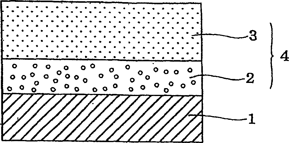
[0177] 1 part by weight of α-titanyl phthalocyanine (oxytitanyl phthalocyanine) [SANYO COLORWORKS, LTD., α-TiOPc] was added to 1 part by weight of butyral resin [poly(vinyl butyral) BL-1, manufactured by Sekisui Chemical Co., Ltd. manufactured, hereinafter the same] was dissolved in a binder polymer solution prepared in 30 parts by weight of tetrahydrofuran, and dispersed together with glass beads in a vibration attritor for 5 hours. This dispersion was applied on a sheet formed by vacuum-depositing aluminum on a polyethylene terephthalate (hereinafter abbreviated as "PET") film using a wire rod, followed by drying at 100° C. for 2 hours, thereby A charge generation layer having a thickness of about 2 μm was formed.

[0178] Subsequently, 1 part by weight of Compound 1-3 obtained in Synthesis Example 3 and 1 part by weight of polycarbonate resin, Panlite TS-2020 [manufactured by TEIJIN CHEMICALS LTD.; the same hereinafter] were mixed, and dissolved In 8 parts by weight of 1,2...

Embodiment 2

[0180] The electrophotographic photoreceptor B of the present invention was prepared in the same manner as in Example 1 except that Compound 1-9 was used instead of Compound 1-3.

Embodiment 3

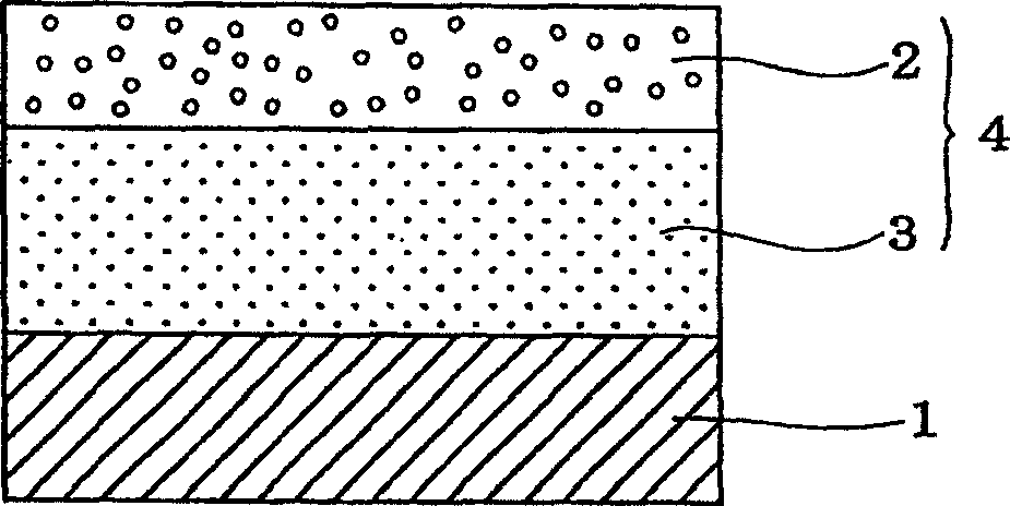
[0196] 1 part by weight of β-titanium phthalocyanine [SANYO COLOR WORKS, LTD., β-TiOPc] was added to 1 part by weight of butyral resin [poly(vinyl butyral) BL-1] dissolved in 30 parts by weight of tetrahydrofuran in the binder polymer solution prepared in the medium and dispersed with glass beads in a vibrating attritor for 5 hours. The dispersion was applied on a sheet comprising a PET film with vacuum-deposited aluminum thereon using a wire rod, followed by drying at 100° C. for 2 hours, thereby forming a charge generation layer having a thickness of about 2 μm.

[0197] Subsequently, 1 part by weight of Compound 1-3 obtained in Synthesis Example 3 was mixed with 1 part by weight of polycarbonate resin, Panlite TS-2020, and dissolved in 8 parts by weight of 1,2-dichloroethylene in alkane. The solution was applied on the previously formed charge generating layer using a doctor blade, and dried at 80° C. for 3 hours to form a charge transporting layer having a thickness of ab...


PUM

PropertyMeasurementUnit
thicknessaaaaaaaaaa
thicknessaaaaaaaaaa

Abstract

A charge transporting material for use in an electrophotographic photoreceptor, which comprises a compound represented by the formula (1); and an electrophotographic photoreceptor using this charge transporting material. As the electrophotographic photoreceptor using the charge transporting material, there are illustrated, for example, a lamination type photoreceptor having a charge generating layer 2 and a charge transporting layer 3 and, as needed, an interlayer 7, and a single layer type photoreceptor. In the formula, R<1> to R<5> each independently represents a hydrogen atom, an alkyl group, a halogen atom, an alkoxy group, an aryl group or a substituted aryl group, and R<6> represents a hydrogen atom, an alkyl group, an aryl group or a substituted aryl group.

Description

technical field [0001] The present invention relates to an electrophotographic photoreceptor which can be advantageously used as a photoreceptor in a copying or recording device based on an electrophotographic system, such as an electrophotographic copier, a laser beam printer, a printing machine with a liquid crystal shutter, In devices such as LED printers, the present invention also relates to charge transport materials used in photoreceptors. Background technique [0002] As a photoconductive material used in an electrophotographic photoreceptor, inorganic materials such as selenium, selenium-tellurium, arsenic triselenide, cadmium sulfide, zinc oxide, or amorphous silicon have conventionally been widely used. However, electrophotographic photoreceptors using such inorganic photoconductive materials suffer from such problems that they are poor in flexibility, sensitive to thermal or mechanical shock, too expensive to produce, and somewhat toxic. [0003] In recent years...

Claims


Application Information

Patent Timeline
Patent Type & Authority Applications(China)
IPC IPC(8): G03G5/06C07C211/54
CPCG03G5/0672C07C211/54G03G5/0614G03G5/06142G03G5/061443G03G5/06147G03G5/06G03G15/02
Inventor 小林透堀容嗣
Owner TAKASAGO INTERNATIONAL CORPORATION
Why Eureka
Try Eureka