
Information storage

一种信息存储、存储媒体的技术,应用在信息存储、静态存储器、数字存储器信息等方向,能够解决体积大、难高密度化、无人使用等问题

Inactive Publication Date: 2006-03-08
PANASONIC CORP
View PDF1 Cites 2 Cited by
  • Summary
  • Abstract
  • Description
  • Claims
  • Application Information

AI Technical Summary

Problems solved by technology

[0005] However, in the above-mentioned prior art information storage device irradiated with electron beams, due to the following disadvantages, it has been replaced by magnetic core memory, and then by semiconductor memory, and no one is using it now.
[0006] (1) The device itself is large in size,
[0007] (2) In order to emit thermal electrons, there must be a heater and a heater power supply,
However, due to the constraints of the semiconductor manufacturing process in the manufacturing process, it is difficult to further achieve rapid high-density problems.

Method used


Image

  • Information storage
  • Information storage
  • Information storage

Examples


Embodiment Construction

[0042] Embodiments of the present invention will be described below with reference to the drawings.

[0043] (Information storage device with 1 information storage unit)

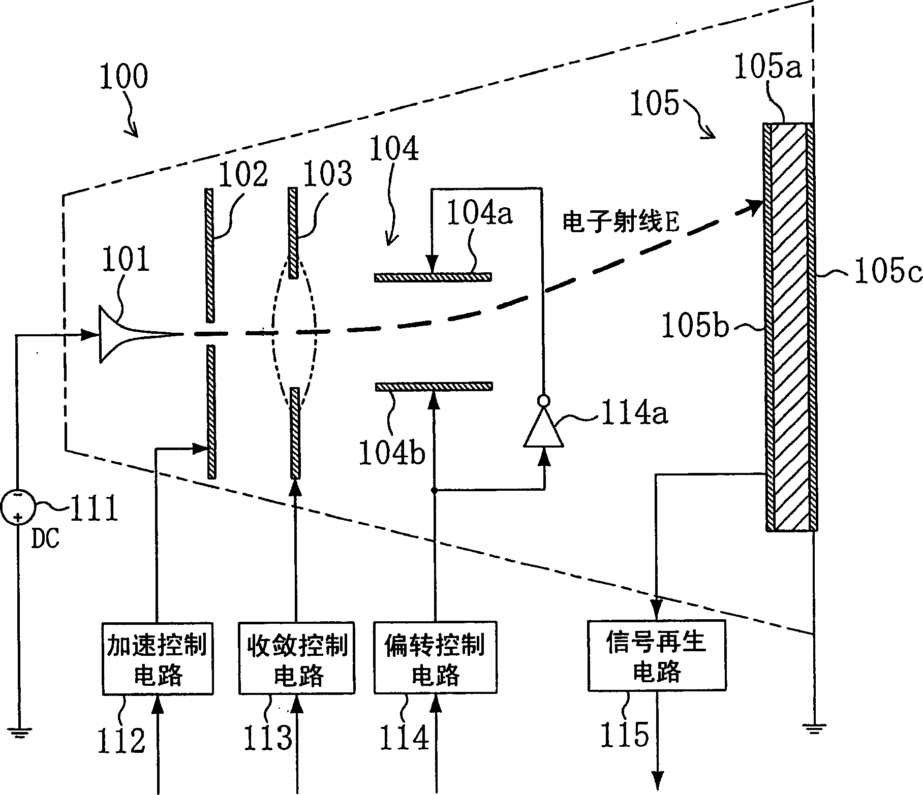
[0044] figure 1 It is a schematic diagram showing the configuration of an information storage device including one information storage unit 100 .

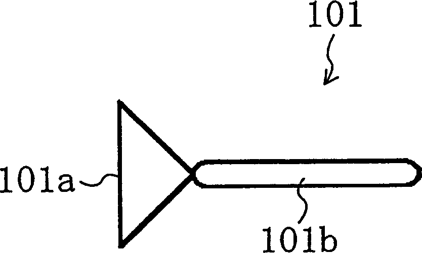
[0045] exist figure 1 Among them, the cold cathode 101 emits electron rays (electron beams) E when a negative voltage is applied by the cathode ray driving circuit 111 . The specific structure of the cold cathode 101 will be described later. In addition, the voltage applied to the cold cathode 101 may be a direct current, or a pulse driving voltage formed of a surge pulse or the like.

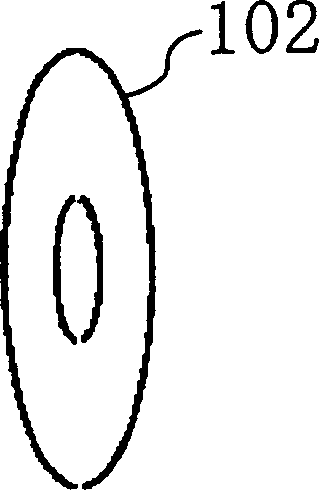
[0046] Accelerating electrode 102, for example by figure 2The ring-shaped electrode configuration shown in the figure, after the acceleration control circuit 112 is applied with a voltage higher than the voltage of the cold cathode 101, under the action of the electric field...


PUM


Abstract

In order to significantly increase a recording density of a storage, an electron beam (E) emitted from a cold cathode (101) is accelerated by an acceleration electrode (102), converged by a convergence electrode (103), deflected by a deflection electrode (104), and made to impinge on a micro region of a memory film (105). The memory film (105) has, for example, a phase change film (105a). When the memory film (105) is irradiated with a high-energy electron beam (E), it is rapidly heated and cooled and becomes an amorphous state. When the memory film (105) is irradiated with a middle-energy electron beam (E), it is slowly cooled and crystallized thereby to store data. When the memory film (105) is irradiated with a low-energy electron beam (E), depending on the state of amorphous development or crystallization, a different potential difference between a detection electrode (105b) and an anode (105c) is detected and the stored data is read out.

Description

technical field [0001] The present invention relates to the technology of an information storage device for storing and reading information after a storage medium is irradiated with electron rays. Background technique [0002] As an information storage device for storing and reading information by irradiating a dielectric with electron beams, long before magnetic core memory and semiconductor memory were put into practical use, people tried to use the same CRT (cathode ray tube) as that used for display (for example, U.S. Patent No. 2,755,994, block 2, lines 19-56). It is the same as when displaying images, by applying a negative voltage of several thousand V to the filament in the red-hot state, it emits hot electrons, and irradiates the dielectric (phosphor) with electron rays formed by hot electrons. Read out information. [0003] More specifically, after the deflection-controlled electron beam irradiates the region of the dielectric corresponding to the storage bit, an...

Claims


Application Information

Patent Timeline
Patent Type & Authority Applications(China)
IPC IPC(8): G11C11/30H01J21/10H01J19/24H01J19/32H01J19/38H01J19/40G11C7/00
CPCG11C7/005
Inventor 苅田吉博虫鹿由浩
Owner PANASONIC CORP
Learn More