
Thermal interface material

A technology of thermal interface materials and metal particles, applied in heat exchange materials, electrical components, electrical solid devices, etc., can solve problems such as poor thermal conductivity and insufficient gap filling, to improve thermal conductivity, improve thermal conductivity, The effect of reducing thermal resistance

Inactive Publication Date: 2006-01-04
HONG FU JIN PRECISION IND (SHENZHEN) CO LTD +1
View PDF0 Cites 2 Cited by
  • Summary
  • Abstract
  • Description
  • Claims
  • Application Information

AI Technical Summary

Problems solved by technology

[0005] In order to solve the problem in the prior art that the thermal interface material cannot fully fill the gap between the radiator and the heating element, resulting in poor thermal conductivity, the main purpose of the present invention is to provide a fully gap-filling and Thermal interface material with excellent thermal conductivity

Method used


Image

  • Thermal interface material
  • Thermal interface material
  • Thermal interface material

Examples


Embodiment Construction

[0013] The present invention will be described in detail below in conjunction with the accompanying drawings and specific embodiments.

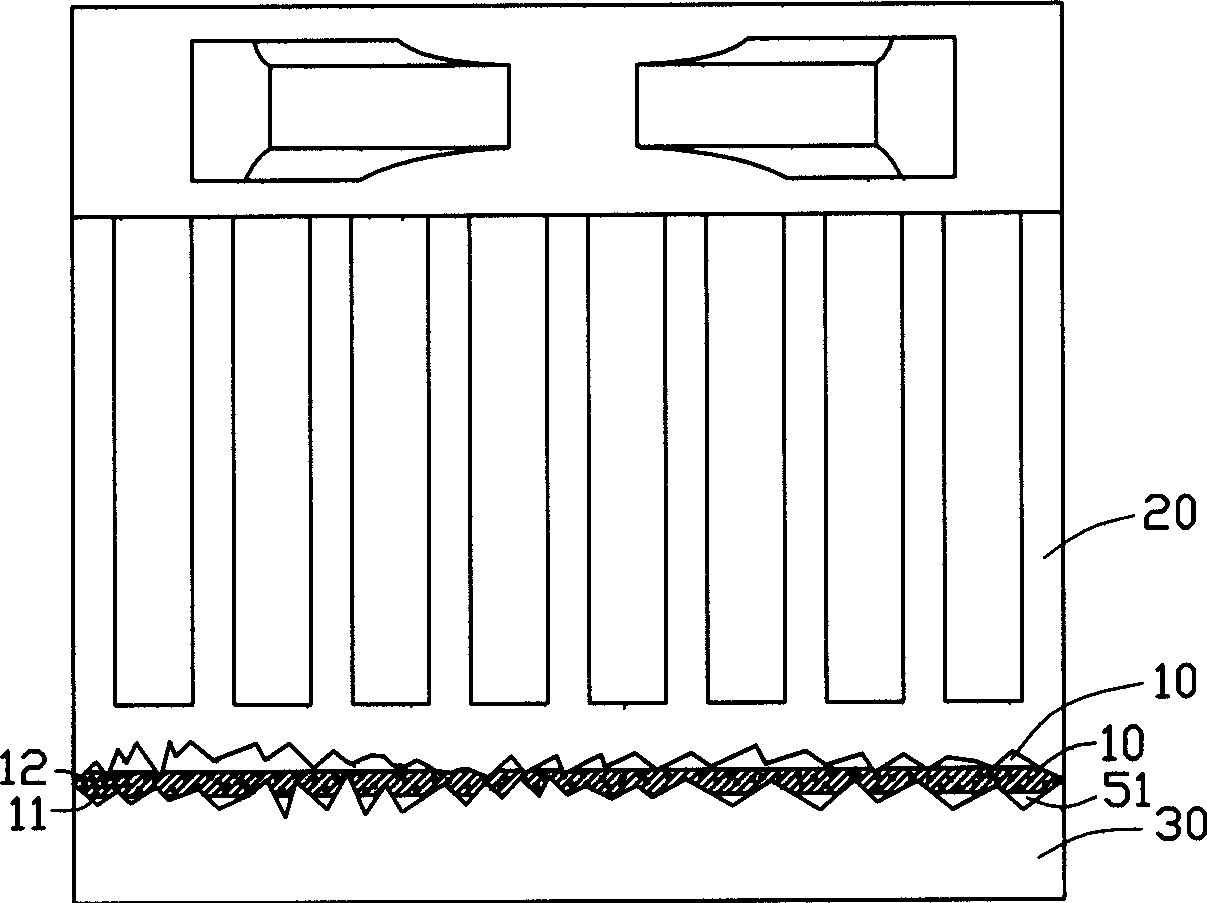
[0014] The present invention provides a thermal interface material, such as image 3 As shown, the thermal interface material 10 includes an interstitial fluid 11 and metal particles 12 distributed therein that can react with air. The metal particles 12 are nanoscale particles with a particle size of 1-100 nm, including one or more of Aluminum, Magnesium, Iron and other particles.

[0015] The interstitial fluid 11 includes oils, fats and gums, the oils include mineral oil, silicone oil, petroleum ointment and vaseline; the fats include animal fats and vegetable oils; the glues include silica gel (Silicone Glue) series, Polyethylene Glycol (Polyethylene Glycol), Epoxy Resin (Epoxy Resin) series, Oxygen-deficient adhesive series, Acrylic adhesive (Acrylic) series, etc.

[0016] The thermal interface material provided by the present invention...


PUM

PropertyMeasurementUnit
particle diameteraaaaaaaaaa

Abstract

The thermal interface material includes gap filling fluid and metal particle dispersed in the fluid and capable of reacting with air. The particle capable of reacting with air is nanometer level particle. Inside the thermal interface material, the metal particle reacts with air in the interval of the heat source and heat dissipating assembly to reduce or even eliminate interval to lower heat resistance and raise heat conducting performance. The reaction product with high heat conducting performance may further improve the heat conducting performance of the thermal interface material.

Description

【Technical field】 [0001] The invention relates to a thermal interface material. 【Background technique】 [0002] In recent years, with the rapid development of the integration process of semiconductor devices, the degree of integration of semiconductor devices has become higher and higher. However, the volume of devices has become smaller and smaller, and their demand for heat dissipation has become higher and higher. more important question. To meet this requirement, various heat dissipation methods such as fan heat dissipation, water-cooled auxiliary heat dissipation, and heat pipe heat dissipation are widely used, and certain heat dissipation effects have been achieved. [0003] see figure 1 , due to the inevitable surface roughness of the radiator 20 and the heating element 30 (heat sources such as semiconductor integrated devices, such as CPU), the gap 50 formed between the radiator 20 and the heating element 30 makes the radiator 20 and the heating element 30 General...

Claims


Application Information

Patent Timeline
Patent Type & Authority Applications(China)
IPC IPC(8): C09K5/18
CPCH01L2924/0002H01L23/3736H01L23/42H01L2924/00
Inventor 简扬昌黄元亨
Owner HONG FU JIN PRECISION IND (SHENZHEN) CO LTD
Learn More