Method of electrodynamics for quick restoring soil polluted by heavy metal in situ
An electrokinetic and polluted soil technology, applied in the restoration of polluted soil, etc., can solve the problems of shortening the processing time, achieve the effects of shortening the processing time, shortening the migration distance, and improving the effect of dissolution
- Summary
- Abstract
- Description
- Claims
- Application Information
AI Technical Summary
Problems solved by technology
Method used
Image

Examples
Embodiment 1
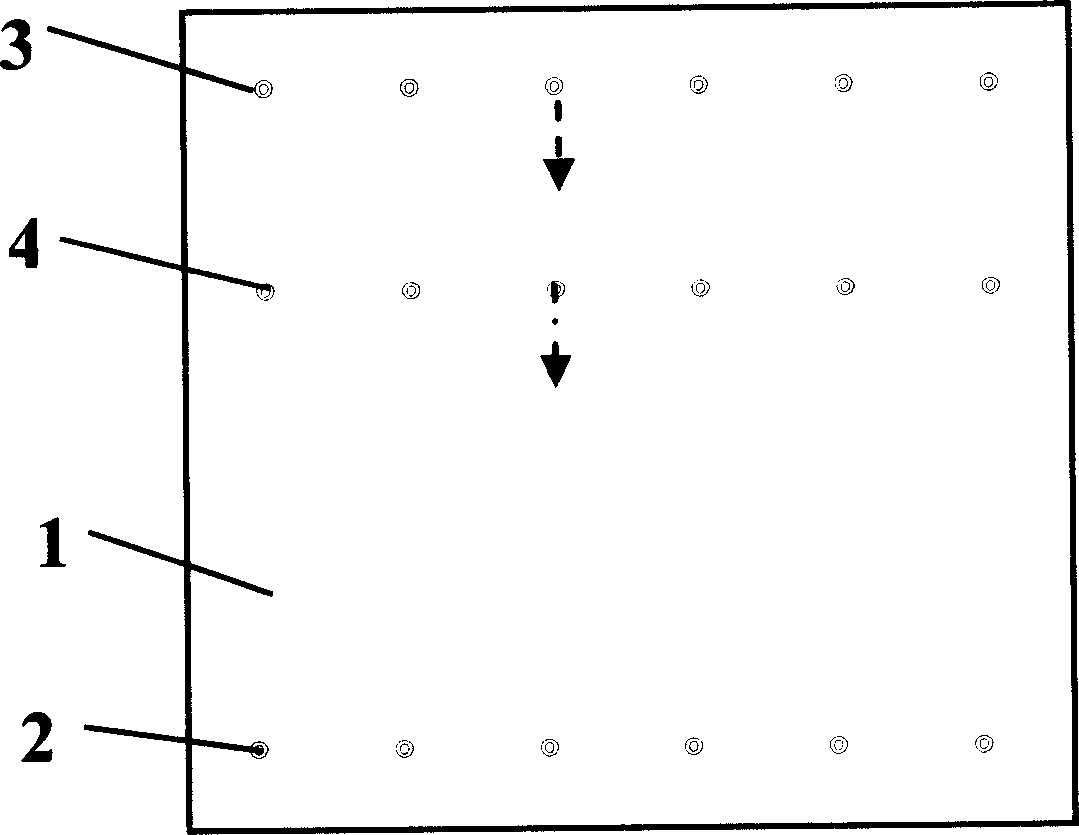
[0023] Treat the 2.5m×2.0m Pb-contaminated soil around the smelter, the soil pollution depth is about 1.5m, and insert a 2.5m×1.5m stainless steel plate with a thickness of 2mm on the enrichment side as the cathode, that is, the enrichment electrode, 20 pieces The high-density graphite rods of φ50mm are divided into two groups as anodes, that is, working electrodes, among which 10 working electrodes are placed on the other side at equal intervals in parallel, and firstly connected with 400V DC with an electric field strength of 200V / m, and then placed in the middle in parallel at equal intervals for 10 a working electrode. Pb in the soil migrated to the enriched electrode region under the potential force. After 30 hours of electric treatment work, energize the 10 working electrodes placed in the middle, and reduce the working voltage to 200V until the soil treatment of the entire working area is completed. The results showed that the Pb content in the soil sample decreased fr...
Embodiment 2
[0025] Select a range of 4.2m×20m in the Cd-contaminated soil around the electroplating plant for treatment. The soil pollution depth is about 1.2m. A 2.0m×1.0m high-density graphite plate with a thickness of 10mm is fixed on the enrichment side as the cathode, that is, the enrichment electrode. , 20 pieces of PbO with a thickness of 3.0mm and 1.2m×0.1m 2 / Ti as the anode, that is, the working electrode, is placed on the other side 20m away from the enrichment side in parallel and equidistant, and first passes through 400V DC with an electric field strength of 20V / m to start the treatment. Cd in the soil migrated to the enriched electrode region under the potential force. After 120 hours of electric treatment work, the anode moves closer to the cathode by 2m, place it well and reduce the working voltage to 360V. After 120 hours of electric treatment, the anode moved forward again by 2m and lowered the working voltage by 40V, and moved forward 9 times in this way to complete th...
Embodiment 3
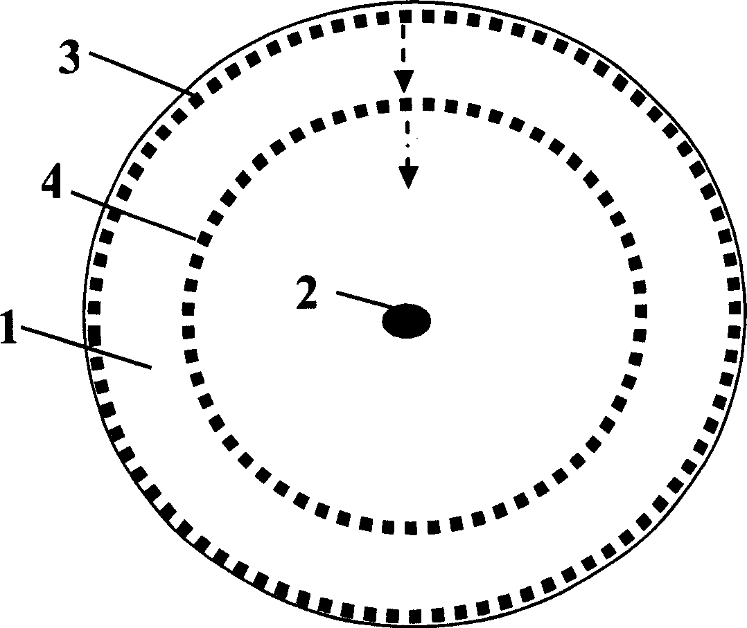
[0027] In the phenol-contaminated soil around the chemical plant, the range of φ2.5m in diameter is selected for treatment, and the soil pollution depth is about 1.6m. Ru / Ti mesh electrodes are placed around the center of the circle to make an anode of φ0.2m and 1.8m in length, that is, enrichment Electrodes, keep 0.2m on the ground. 32 steel pipes with a diameter of 50mm and a length of 1.8m are used as cathodes, that is, working electrodes, and 0.2m is reserved on the ground. They are placed in a circle with a distance of about 0.19m, and placed on the outermost side. First, 250V DC is passed through, and the electric field strength is 100V / m. Phenol in the soil migrated to the enriched anode region under the force of potential and was anodized. After 10 hours of electric treatment, move each cathode closer to the anode by 0.2m, keep the distance between the cathodes 0.15m-0.20m, remove the excess cathode, and reduce the electric field intensity to 230V. After another 10 ho...
PUM
 Abstract
Description
Claims
Application Information
 - R&D
- Intellectual Property
- Life Sciences
- Materials
- Tech Scout
- Unparalleled Data Quality
- Higher Quality Content
- 60% Fewer Hallucinations
Browse by: Latest US Patents, China's latest patents, Technical Efficacy Thesaurus, Application Domain, Technology Topic, Popular Technical Reports.
© 2025 PatSnap. All rights reserved.Legal|Privacy policy|Modern Slavery Act Transparency Statement|Sitemap|About US| Contact US: help@patsnap.com