
Adhesive for sealing organic electroluminescent element and use thereof

An electroluminescent element and sealing technology, applied in electroluminescent light sources, electrical components, adhesives, etc., can solve the problems of increased residual stress, insufficient curing of photocurable adhesives, and reduced component performance.

Inactive Publication Date: 2005-08-31
SEKISUI CHEM CO LTD
View PDF6 Cites 29 Cited by
  • Summary
  • Abstract
  • Description
  • Claims
  • Application Information

AI Technical Summary

Problems solved by technology

[0007] But the problem is that in the method of sealing with an airtight container, the thickness increases due to the airtight container, and the weight also increases
In addition, in the method of covering with a protective film of silicon oxide or silicon nitride, during element maintenance (by means of laser or the like to burn damaged elements and turn them on) or during manufacturing operations, there is a need to prevent damage caused by object collision. It is necessary to increase the film thickness, but when the film thickness is increased, the residual stress will increase, which will cause the substrate to warp, or cracks will appear to cause the characteristics to deteriorate. In addition, when the film thickness is increased, the film formation time will be extended
[0008] In addition, when sealing with a photocurable adhesive or a thermosetting adhesive, the organic EL element is easily exposed to heat or light when the adhesive is cured, so that the performance of the element tends to deteriorate, and sometimes the Deterioration occurs
In addition, when using a photocurable adhesive, the gas generated when light is irradiated fills the element and promotes element deterioration. When there is a part that cannot be exposed to light due to metal wiring, or when sealing a When the substrate is placed, the curing of the photocurable adhesive becomes insufficient

Method used


Image

  • Adhesive for sealing organic electroluminescent element and use thereof
  • Adhesive for sealing organic electroluminescent element and use thereof
  • Adhesive for sealing organic electroluminescent element and use thereof

Examples


Embodiment 1~3、 comparative example 1~2

[0119] (1) Preparation of organic EL element substrate 1

[0120] An ITO electrode film was formed to a thickness of 1000 Å on a glass substrate (25 mm×25 mm×0.7 mm), and the formed member was used as a transparent supporting substrate. Use acetone, alkaline aqueous solution, ion-exchanged water, and isopropanol to carry out ultrasonic cleaning to the above-mentioned transparent support substrate for 15 minutes respectively, then clean with boiling isopropanol for 10 minutes, and then use a UV-ozone cleaner (NL-UV253, Japan Laser Electronics Co., Ltd.) for pretreatment. Next, fix the transparent support substrate on the substrate holder of the vacuum evaporation device, put N, N'-bis(1-naphthyl)-N, N'-diphenylbenzidine (α -NPD) 200mg, put tris(8-hydroxyquinoline) aluminum (Alq3) 200mg in other bisque crucible, reduce the pressure in the vacuum chamber to 1×10 -4 Pa. Then, the crucible containing α-NPD was heated, and α-NPD was deposited on the substrate at a deposition rate...

Embodiment 4~9

[0139] (Examples 4-9, Comparative Example 3)

[0140] (2) Fabrication of the organic EL element substrate 2

[0141] Using the same method as in Example 1, after cleaning the glass substrate (25 mm x 25 mm x 0.7 mm), an aluminum electrode film was formed to a thickness of 1000 Å as a transparent supporting substrate. Next, fix the transparent support substrate on the substrate holder of the vacuum evaporation device, put 200 mg of α-NPD into the first bisque crucible, put 200 mg of Alq3 into the second bisque crucible, and heat the Put 200mg of lithium fluoride in the boat, and reduce the pressure in the vacuum chamber to 1×10 -4 Pa. Subsequently, lithium fluoride was formed into a 5 Å thick film at a deposition rate of 0.2 Å / s, and then Alq3 was formed into a 600 Å thick light emitting layer at a deposition rate of 15 Å / s. Next, α-NPD was deposited on the substrate at a deposition rate of 15 Å / s to form a hole transport layer with a film thickness of 600 Å. Then, the tran...

Embodiment 10

[0154] (1) Production of organic EL elements

[0155] An ITO electrode was formed into a film with a thickness of 100 nm on a glass substrate of 25 mm×25 mm×0.7 mm, and the formed member was used as a transparent supporting substrate. Use acetone to carry out ultrasonic cleaning for 15 minutes, carry out ultrasonic cleaning with alkaline aqueous solution for 15 minutes, then carry out ultrasonic cleaning with isopropanol for 15 minutes, and then use boiling isopropanol to clean for 10 minutes, and then use a UV-ozone cleaner ( "NL-UV253" manufactured by Nippon Laser Electronics Co., Ltd.) was pretreated. Next, this transparent support substrate was fixed on a substrate holder of a commercially available vacuum evaporation device (manufactured by Nippon Vacuum Technology Co., Ltd.), and N,N'-bis(1-naphthyl)-N was placed in a bisque crucible, 200 mg of N'-diphenylbenzidine (α-NPD), and 200 mg of tris(8-hydroxyquinoline) aluminum (Alq3) were placed in other bisque crucibles, and...


PUM


Abstract

It is an object of the present invention to provide an adhesive for sealing an organic electroluminescence device, an adhesive tape for sealing an organic electroluminescence device, a double-faced adhesive tape for sealing an organic electroluminescence device, a method of sealing an organic electroluminescence device and an organic electroluminescence device, which can seal an organic electroluminescence device without degrading it with light or heat. The present invention relates to an adhesive for sealing an organic electroluminescence device, which comprises a photo cationic polymerizable adhesive containing a photo cationic polymerizable compound and a photo cationic polymerization initiator and, initiating a curing reaction by light irradiation and proceeding the curing reaction by a dark reaction even after interrupting the light irradiation.

Description

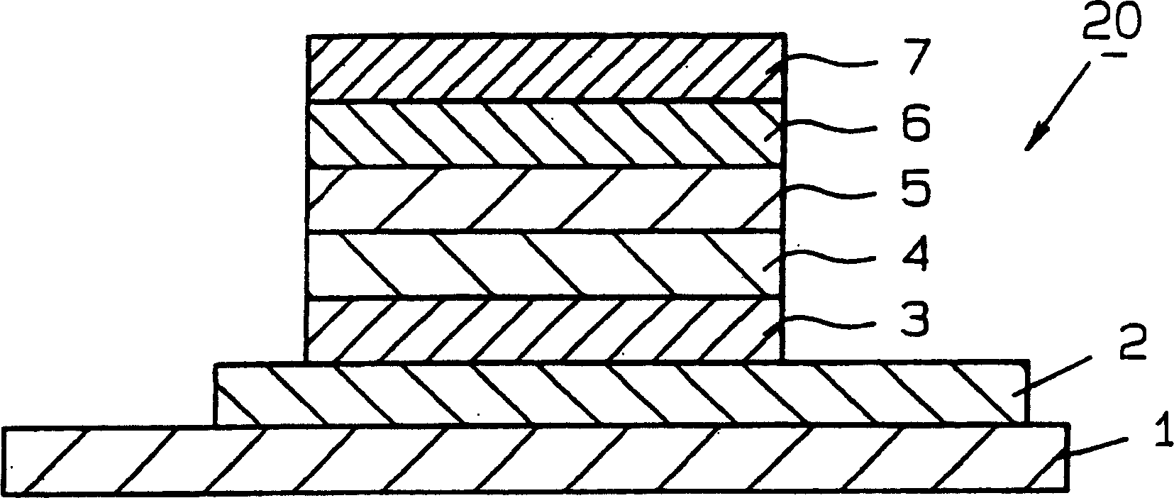
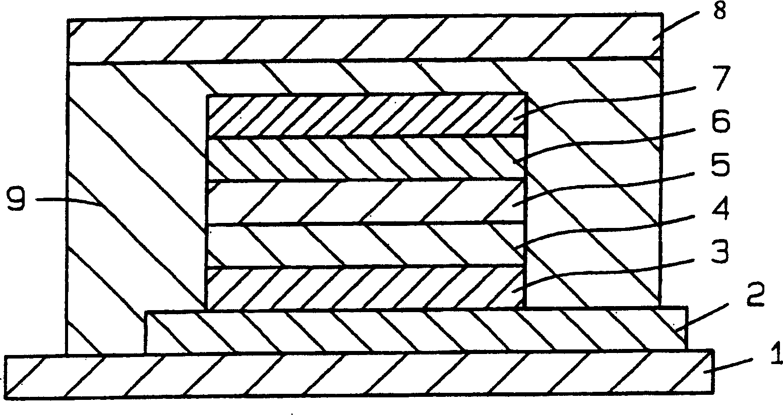
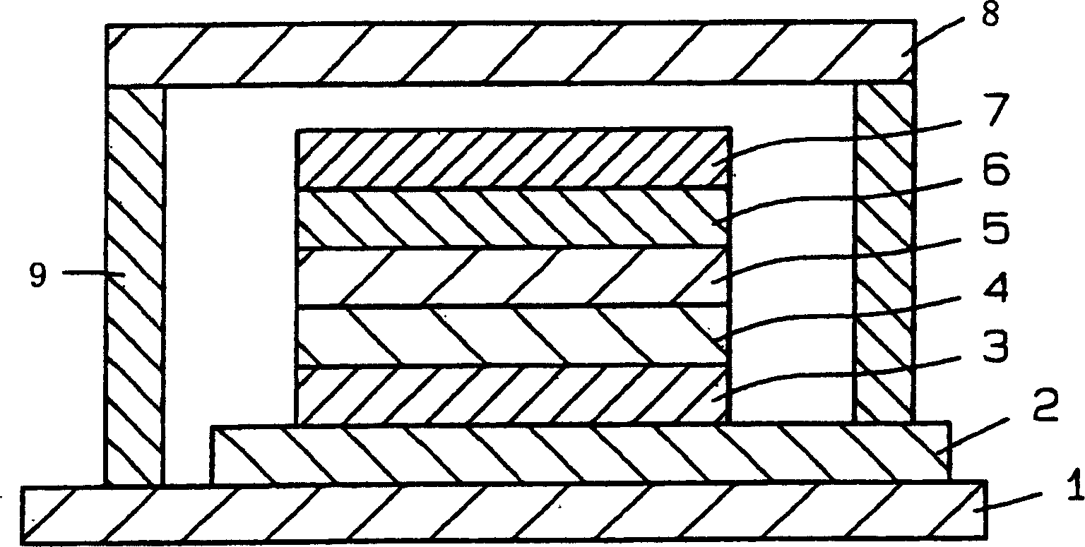
technical field [0001] The present invention relates to an adhesive for sealing organic electroluminescence elements, an adhesive tape for sealing organic electroluminescence elements, A double-sided adhesive tape for sealing an organic electroluminescent element, a sealing method for an organic electroluminescent element, and an organic electroluminescent element. Background technique [0002] An electroluminescent element (hereinafter referred to as an organic EL element) using an organic electroluminescent material (hereinafter referred to as an organic EL material) in the light-emitting layer is usually formed by sequentially stacking holes on one electrode provided on a substrate. layer, a light emitting layer, an electron injection layer, and a thin film structure on which other electrodes are provided. figure 1 is a schematic cross-sectional view showing an example of such a thin film structure. figure 1 The thin film structure 20 shown is that a hole injection elec...

Claims


Application Information

Patent Timeline
Patent Type & Authority Applications(China)
IPC IPC(8): G03F7/038H01L51/52
CPCG03F7/038H01L51/5237Y10T428/31511H10K50/846H10K50/8426H10K50/844C09J201/00C09J163/00
Inventor 岛津宏宣七里德重
Owner SEKISUI CHEM CO LTD
Learn More