Ultrasonic processor
A processor and ultrasonic transducer technology, applied in the field of continuous multifunctional ultrasonic processors, can solve the problems of weakening the effect of ultrasonic functions and mutual interference
- Summary
- Abstract
- Description
- Claims
- Application Information
AI Technical Summary
Problems solved by technology
Method used
Image
Examples
Embodiment 1
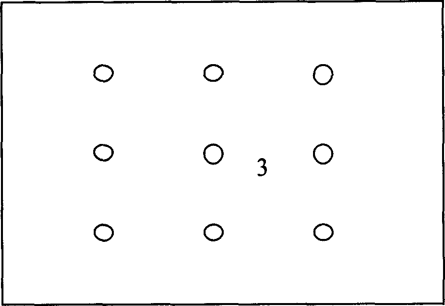
[0029] Put water and edible strawberry flavor according to (water: essence = 100: 10 (kg / g)) through the feed port, and turn on the switch of the ultrasonic generator. The selected ultrasonic frequency is 15kHz, one ultrasonic generator forming the ultrasonic processor of the present invention, each power of 6 ultrasonic transducers is 5-500W, and each of the six ultrasonic transducers is distributed on each of the six walls of the cube container. , and no symmetry; each transducer generates a sine wave, and the material stays in the processor for 10 seconds at a temperature of 40°C. The material is directly connected to the yogurt or beverage production line at the discharge port. After testing, the emulsification is thorough. Preservation for 35 days did not produce separation phenomenon.
Embodiment 2
[0031] Put the pulverized (20-mesh sieve) tea leaves and water into the container according to tea: water = 1:20 (kg / kg), turn on the switch of the ultrasonic generator, select the ultrasonic frequency 25kHz, the total power is 15 ~ 2500W, 5 ultrasonic waves The power of each transducer is 5-500W, and one is distributed on each of the five walls of the cube container, and there is no symmetry; each transducer generates a sine wave, and the temperature is 85°C. The material stays in the processor for 8 seconds. A separator is connected to the discharge port to concentrate the solution or directly use it in beverage production. After testing, the light absorption value of the solution at the discharge port reaches the maximum, and the light transmittance is the minimum.
Embodiment 3
[0033] Put zein and ethanol 1:10 (kg / kg) into the processor, select 2 ultrasonic transducers with frequencies of 15kHz, 25kHz, and 48kHz each, and each of the 6 ultrasonic transducers has a power of 5-150W. Power 15-900W; distributed on each of the six walls of the cube container, there is no symmetry; each transducer generates a sine wave, the temperature is 50 ° C, the time is 15 minutes, and the discharge port is connected to the separator for separation After testing, zeaxanthin and gliadin were completely extracted.
[0034] It can be seen from the above examples that the ultrasonic functional device of the present invention has been practically applied by the School of Food and Bioengineering of South China University of Technology, and compared with the prior art equipment, it has obvious advantages after evaluating the practical effect, and its characteristics are as follows:
[0035] 1. Increase production. The traditional method is a batch reaction, but now it is a ...
PUM
 Abstract
Description
Claims
Application Information
 - R&D
- Intellectual Property
- Life Sciences
- Materials
- Tech Scout
- Unparalleled Data Quality
- Higher Quality Content
- 60% Fewer Hallucinations
Browse by: Latest US Patents, China's latest patents, Technical Efficacy Thesaurus, Application Domain, Technology Topic, Popular Technical Reports.
© 2025 PatSnap. All rights reserved.Legal|Privacy policy|Modern Slavery Act Transparency Statement|Sitemap|About US| Contact US: help@patsnap.com


