
Active and passive Q-adjusted single longitudinal mode laser

A laser, single longitudinal mode technology, used in lasers, laser parts, phonon exciters, etc., can solve the problems of unable to obtain stable repetition frequency, unable to guarantee long-term stability of injection locking, and destruction of repetition frequency stability.

Inactive Publication Date: 2005-07-27
INST OF PHYSICS - CHINESE ACAD OF SCI
View PDF1 Cites 34 Cited by
  • Summary
  • Abstract
  • Description
  • Claims
  • Application Information

AI Technical Summary

Problems solved by technology

However, injection locking requires that the detuning between the frequency of the injected signal and the frequency of the closest longitudinal mode in the sub-cavity must be less than a certain value, otherwise injection locking will fail
Therefore, in injection locking, there must be an electronic system for feedback control of the cavity lengths of the main cavity and the auxiliary cavity. This system is technically complex, and it still cannot guarantee the long-term stability of injection locking.
[0010] Both active Q-switching and passive Q-switching can achieve single longitudinal mode laser output. Under pulse or continuous pumping conditions, active Q-switching single longitudinal mode laser can be obtained by using pre-laser technology, but the probability of single longitudinal mode is low
In order to improve the working probability of the single longitudinal mode, a detection device is required to detect the formation of the pre-laser pulse, which destroys the stability of the repetition rate, and the cavity length of the active Q-switched pre-laser single longitudinal mode laser needs to use piezoelectric ceramics control, making the system more complex and less practical
The device of passive Q-switched single longitudinal mode laser is simple and easy to use, but it cannot obtain a stable repetition rate and can only work near the threshold. Dong Jun reported a single longitudinal mode laser output with an average power of up to 80 mW in 2000 ( Microwave and Optical Technology Letters, Vol.26, pp124, 2000)

Method used


Image

  • Active and passive Q-adjusted single longitudinal mode laser
  • Active and passive Q-adjusted single longitudinal mode laser
  • Active and passive Q-adjusted single longitudinal mode laser

Examples


Embodiment Construction

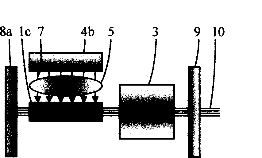
[0049] figure 1 It is the basic embodiment of the active-passive Q-switched solid-state single longitudinal mode laser of the present invention. Since the length of the resonant cavity can be changed, and the laser crystal, saturable absorption crystal and active Q switch in the resonant cavity can be composed in many ways, the Cr 4+ , Nd:YAG as double-doped crystal, acousto-optic Q switch as active Q switch, and flat resonant cavity structure are just examples to illustrate the present invention.

[0050] Double-doped crystal (1)Cr 4+ , Nd:YAG uses double-doped active ion Nd 3+ and saturated absorbing ions Cr 4+ The yttrium aluminum garnet YAG acts as both a laser crystal and a passive Q switch. Activated ion Nd 3+ The doping concentration is 1atm%, and the saturated absorption ion Cr 4+ The doping concentration varies from 0.01 to 0.5 atm%. When the laser oscillation condition is satisfied, that is, the laser can emit oscillating laser light, the Cr 4+ The level of t...


PUM

PropertyMeasurementUnit
Lengthaaaaaaaaaa

Abstract

The invention consists of pumping source, cavity, and a group of coupling device set between the pumping source and cavity, and connected with pumping source through optical fiber. The cavity consists of front cavity mirror and back cavity mirror coated with film. The double-doped crystals and active Q-switch are set between the front and back mirrors. A cooling device is set on the double-doped crystals. The invention features using active Q-switch to control the passive Q-switch for getting prelase pulse, and using saturable absorption crystals as longitudinal mode selector for making the solid single longitudinal mode laser work under higher pumping power.

Description

technical field [0001] The invention relates to a single longitudinal mode laser, in particular to an all-solid-state active-passive Q-switched single longitudinal mode laser using a semiconductor laser as a pump source. Background technique [0002] In many application fields such as coherent lidar, micromachining, laser ranging, trace element detection, microsurgery, laser pulse shaping and energy amplification, if the laser pulse has: stable high repetition rate, high peak power, High average power, short pulse width, small pulse intensity drift and pulse shape change, stable single transverse mode and single longitudinal mode, polarization or partial polarization, no mode competition and mode hopping phenomenon, etc., all or part of these characteristics, this It will be more widely used. Q-switching is a common technique for generating laser pulses with high peak power and short pulse duration. The function of the Q switch is to prevent the laser oscillation in the la...

Claims


Application Information

Patent Timeline
IPC IPC(8): H01S3/00H01S3/042H01S3/08H01S3/0941H01S3/127H01S3/16
Inventor 许祖彦王学军
Owner INST OF PHYSICS - CHINESE ACAD OF SCI
Learn More