
Connection method for tube plate and pipe joint of tube-shell/tube-sheet type heat exchanger

A technology for heat exchangers and pipe joints, used in heat exchange equipment, welding media, welding equipment, etc., can solve the problems of high manufacturing cost, low production efficiency, and high repair rate, and achieve low manufacturing cost, high compactness, and high quality. stable effect

Active Publication Date: 2005-06-22
ZHEJIANG YINLUN MACHINERY
View PDF0 Cites 22 Cited by
  • Summary
  • Abstract
  • Description
  • Claims
  • Application Information

AI Technical Summary

Problems solved by technology

This kind of joint is mostly used in the production of large-scale shell-and-tube / fin-type heat exchangers with a cooling pipe diameter greater than 6 mm. The equipment investment is quite large, and the joints with dense finished products have about 10% leakage rate and high repair rate, difficult repair, high requirements for parts manufacturing precision, high manufacturing cost, can not meet the requirements of today's society for product manufacturing technology and quality
2. The method of fusion welding, that is, using a variety of fusion welding processes and related welding materials to melt the edge of the tube plate opening and the end of the pipe at the same time and form a molten pool with the molten filling material, and form a dense joint after solidification , this method is mostly used in the production of boiler heat exchangers with high temperature, high pressure and heavy load, and is only suitable for small batch production. connect
The quality of the heat exchanger manufactured by this process is stable, clean and beautiful, but the equipment investment is large, the production efficiency is low, and the energy consumption is large. It is suitable for large-scale production of shell-and-tube / tube-fin heat exchangers.

Method used


Image

  • Connection method for tube plate and pipe joint of tube-shell/tube-sheet type heat exchanger

Examples


Embodiment 1

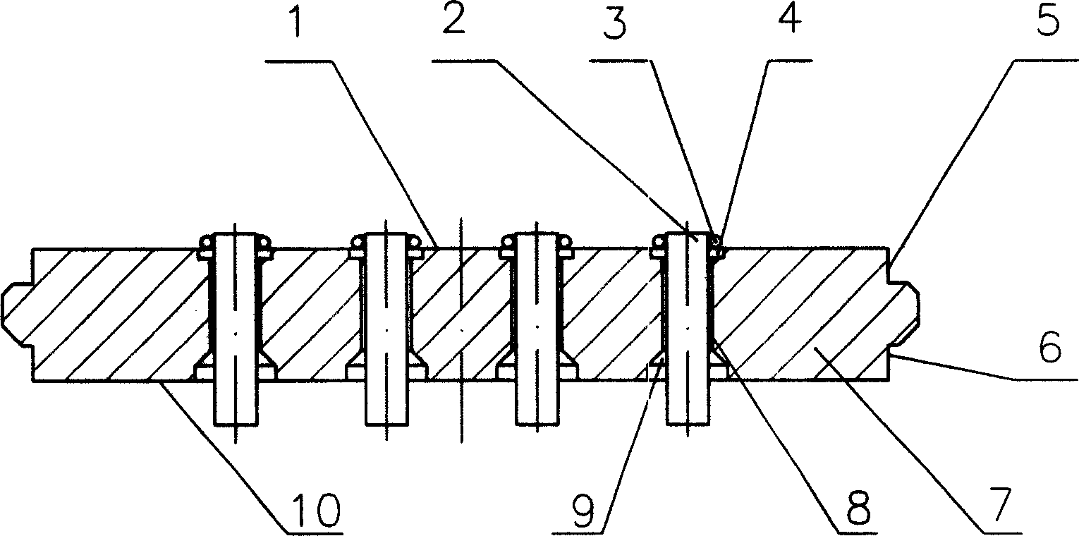
[0013] refer to figure 1 , GK91X397-00-00 type shell-and-tube heat exchanger, the tube sheet 7 is made of low carbon steel, and a set of longitudinal through holes 8 are opened on it, and the bottom of the through holes 8 corresponds to 10 places on the inner surface of the tube sheet A guide counterbore 9 is opened, and the top of the through hole 8 corresponds to the outer surface 1 of the tube sheet, and a welding ring preset counterbore 4 is opened, and the pipe joint part 2 of the heat dissipation pipe penetrates into the through hole 8 for positioning, and then Follow these steps:

[0014] 1) Preset BAg40CuZnSnNi silver-based solder ring 3 in the preset sink hole at the opening of the tube plate, the wire diameter of the solder ring 3 is 1mm, the inner diameter of the solder ring is 5.4mm, and the axial dimension of the solder ring is 1mm ;

[0015] 2) Spray an appropriate amount of brazing flux saturated aqueous solution (QJ102) on the pipe joint; the brazing flux typ...


PUM

PropertyMeasurementUnit
diameteraaaaaaaaaa

Abstract

This invention relates to a tube plate and tube connection method of tube shell and tube pad heat exchanger in each energies systems, which comprises the following steps: 1, pre-setting solder ring to the pre-set hole in the tube plate; 2, coating proper solder dose on the tube connection part; 3, putting the tube plate and inside tube onto the workbench of the middle frequency inducing solder welding machine bed and using PLC elements to control the workbench two coordinates accurate movement and heating the tube plate and tube parts till the dose is melted to fill the welding gaps; 4, automatically spray the cold water onto the machine bed to remove the solder dose.

Description

technical field [0001] The invention relates to the connection method between the tube plate and the tube joint of the shell-and-tube or tube-fin heat exchanger in various active systems, especially the shell-and-tube type heat exchanger whose material is copper and the material of the tube plate is low-carbon steel. The connection method of the tube sheet and the tube joint of the fin heat exchanger. Background of the invention [0002] Shell-and-tube / fin-tube heat exchangers are widely used in various dynamic systems due to their simple structure and convenient manufacture. Usually, the structure of tube-fin / shell-and-tube heat exchangers includes heat pipes, tube sheets, heat dissipation The inlet and outlet passages of fins, shells, spoilers, and different heat exchange media. The airtight connection between the radiating tubes and the holes of the tube plate allows different heat exchange media to exchange heat in mutually independent systems operating separately. Gen...

Claims


Application Information

Patent Timeline
Patent Type & Authority Applications(China)
IPC IPC(8): B23K1/002B23K35/38F28F9/18
Inventor 徐作安冯宗会周益明胡永明文向战谢林传
Owner ZHEJIANG YINLUN MACHINERY
Learn More