
Pneumatic powder spraying apparatus

A technology of aerodynamic spraying and spraying device, applied in liquid spraying device, spraying device, pressure inorganic powder coating and other directions, can solve the problems of increasing the size and weight of the heater, difficult to install the heating element, reducing the working efficiency of the device, etc. Achieve the effect of improving spraying efficiency, broadening industrial application fields and simplifying equipment maintenance

Inactive Publication Date: 2005-04-06
INST OF METAL RESEARCH - CHINESE ACAD OF SCI +1
View PDF1 Cites 26 Cited by
  • Summary
  • Abstract
  • Description
  • Claims
  • Application Information

AI Technical Summary

Problems solved by technology

The main structure of the above-mentioned device includes a compressed gas source, a powder feeder, a supersonic nozzle, a working gas heater, and a powder particle speed regulating system (including a control valve). The structural disadvantage of the above-mentioned device lies in its technical and functional limitations. In fact, the heater made of long pipes has a working gas circulation pipe inside, which increases the size and weight of the heater and complicates its flexible use
[0003] Gas-powered powder spraying device, Russian patent, patent number 2190695 (ПатентРФ № 2190695, МКИC 23C 26 / 00, 20.04.2000 Γ .), consisting of a spraying mechanism and a control device, the two are connected by a hose. The sonic nozzle and the heater are not coaxially fixed, the powder is sent from the powder feeder to the nozzle by the hose, and the electric heating insulator of the gas heater is directly connected to the gas conduit, making it difficult to install the heating element in it, and in the pipe of the electric heating insulator Machining parallel ventilation pipes also increases the technical difficulty, and the out-of-axis of supersonic nozzle and gas heater reduces the working efficiency of the device

Method used


Image

  • Pneumatic powder spraying apparatus
  • Pneumatic powder spraying apparatus
  • Pneumatic powder spraying apparatus

Examples


Embodiment 1

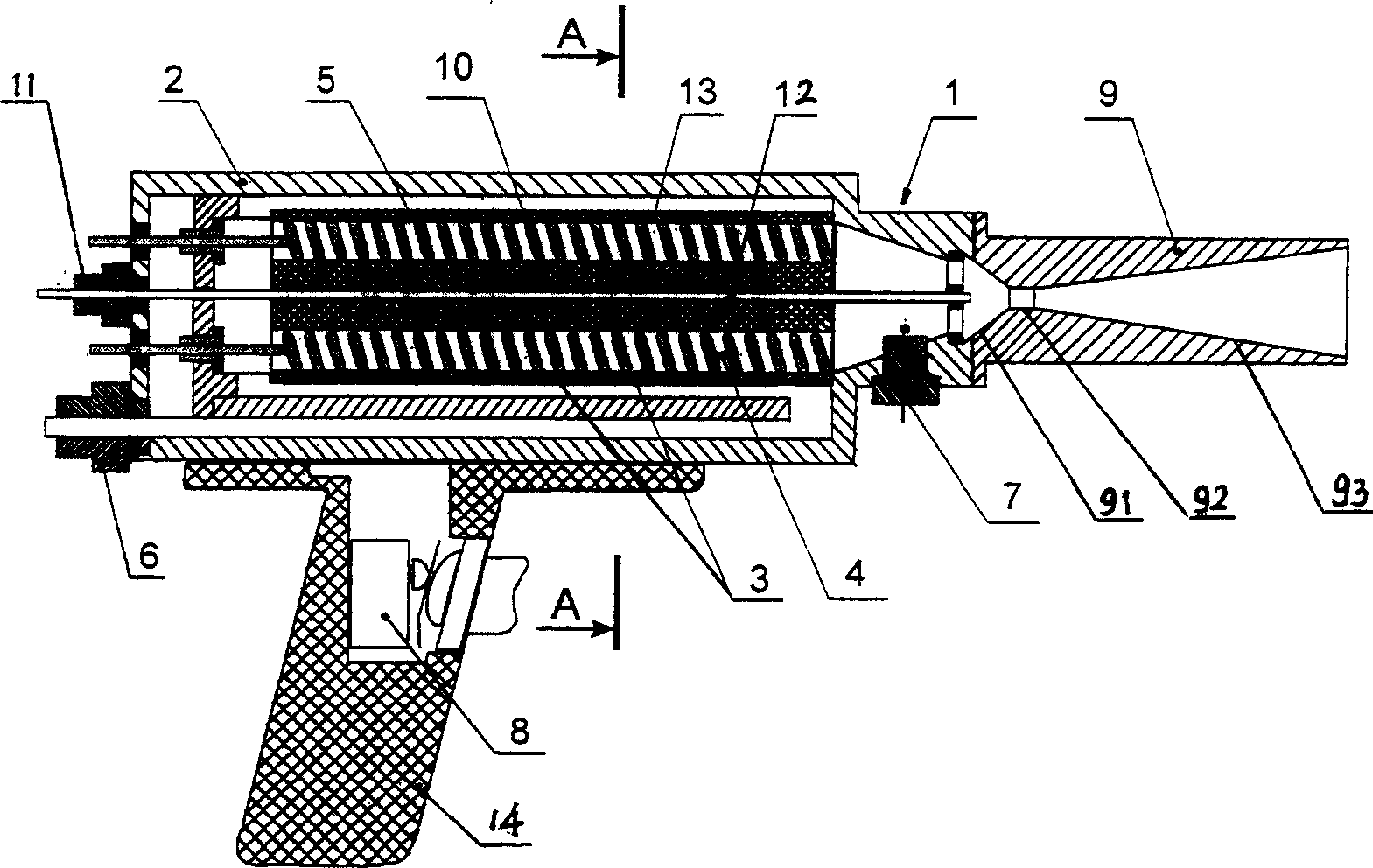
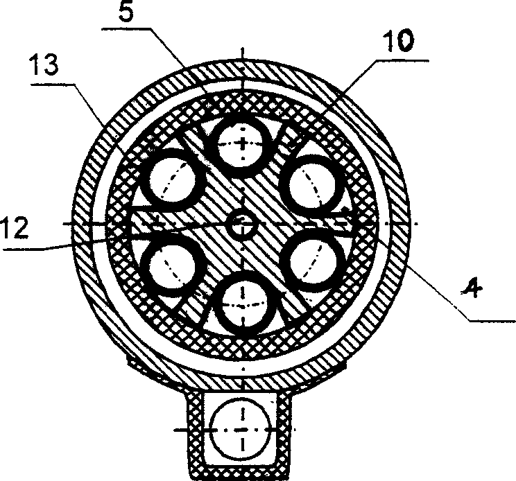
[0024] Pneumatic powder spraying device is composed of compressed air source, powder feeder, portable spraying mechanism for remote operation, ventilation hose and cable connection part, operation control part and so on. like Figure 1~2 As shown, the portable spraying mechanism for remote operation consists of a gas heater 1, a metal shell 2, an electric insulator 3, a grooved gas straight-through channel 4, a heating element 5, a carrier gas connector 6, a temperature sensor 7, and a powder feeding control button 8. The supersonic nozzle 9 rigidly connected with the gas heater 1, the inner cylinder 10, the powder feeding joint 11, the powder feeding pipeline 12, the outer cylinder 13, the handle 14, etc., the gas heater 1 and the supersonic nozzle of the spraying mechanism 9 is a rigid connection structure arranged coaxially. The gas heater 1 includes a metal shell 2, a heating element 5 and an electric heating insulator 3. The heating element 5 and the electric heating insu...

Embodiment 2

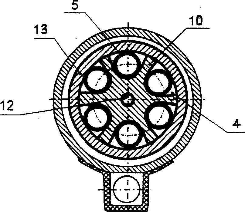
[0029] and Example 1 figure 2 The differences are:

[0030] like image 3 As shown, the inner and outer cylinders 10, 13 of the electrothermal insulator 3 are metal cylinders with an electrothermal insulation coating or surface-treated non-ferrous metal alloy (such as micro-arc oxidation treatment).


PUM


Abstract

This invention opens one kind of gas dynamic powder spraying device which is composed with compression gas source,powder feed unit and spray mechanism.The spray mechanism includes gas heater and supersonic nozzle that is rigid linkage structure of coaxial setting.Gas heater includes metal shell,heat element and electrothermal insulator.One end of metal shell is fixed coaxial with the supersonic nozzle,the other end of metal shell is equipped with carrier gas joint and feed powder joint.The electrothermal insulator which is installed in the metal shell is composed with two coaxial emboitement internal and external tube,the center of the internal tube has a channel which two ends respectively connect powder feed unit and supersonic nozzle.In the exine of the internal tube,there are agroove gas direct channels which connect to the compress gas source,the heat element lies in the agroove gas direct channals.This invention which can be used to prepared monolayer and multi-layer coating widens industry application,reduces equipment weight,simplifies design structure and equipment maintanance and improves the spraying efficiency,being suitable for mechanical energy and metallurgy etc.

Description

technical field [0001] The invention relates to surface spraying treatment of materials, in particular to a gas power powder spraying device. Background technique [0002] In the prior art, relevant patent documents related to gas power spraying device: 1. Russian patent, patent number 1674585 (ΠатентРФ № 1674585, MKИC 23C 26 / 00, 1989.); 2. Chinese patent application, application number 01128130.8. The main structure of the above-mentioned device includes a compressed gas source, a powder feeder, a supersonic nozzle, a working gas heater, and a powder particle speed regulating system (including a control valve). The structural disadvantage of the above-mentioned device lies in its technical and functional limitations. In fact, the heater made of a long conduit has a working gas circulation pipe inside, which increases the size and weight of the heater and complicates its flexible use. [0003] Gas-powered powder spraying device, Russian patent, patent number 2190695 (Патент...

Claims


Application Information

Patent Timeline
Patent Type & Authority Applications(China)
IPC IPC(8): C23C24/04B05B7/14B05B7/16
Inventor 熊天英吴杰金花子卡莎列夫·弗拉吉米尔·弗多洛维奇拉夫鲁申·维克多·弗拉吉米尔洛维奇斯别司采夫·瓦西里·帕夫洛维奇
Owner INST OF METAL RESEARCH - CHINESE ACAD OF SCI
Learn More