Base plate treater

A substrate processing device and substrate technology, applied in the direction of pretreatment surface, device for coating liquid on the surface, optics, etc., can solve the problems of low object detection accuracy, inability to set delay time, poor coating, etc., to prevent Reduced detection accuracy, prevent false detection, and realize the effect of detection accuracy

Active Publication Date: 2005-03-09
DAINIPPON SCREEN MTG CO LTD
View PDF0 Cites 8 Cited by
  • Summary
  • Abstract
  • Description
  • Claims
  • Application Information

AI Technical Summary

Problems solved by technology

[0006] (3) Applying by dragging foreign matter, which becomes the cause of poor coating
When detecting an object with a laser sensor, in order to prevent vibration, a certain delay time is usually set. However, when the detection must be performed in a very short time as described above, there is a problem that the delay time cannot be set.
That is, the existing coating device has a problem that the detection accuracy of the object is lowered due to vibration

Method used


Image

  • Base plate treater
  • Base plate treater
  • Base plate treater

Examples


Embodiment Construction

[0059] The preferred implementation forms of the present invention will be described in detail below with reference to the accompanying drawings.

[0060] 1. The first form of implementation

[0061] 1.1. Description of composition

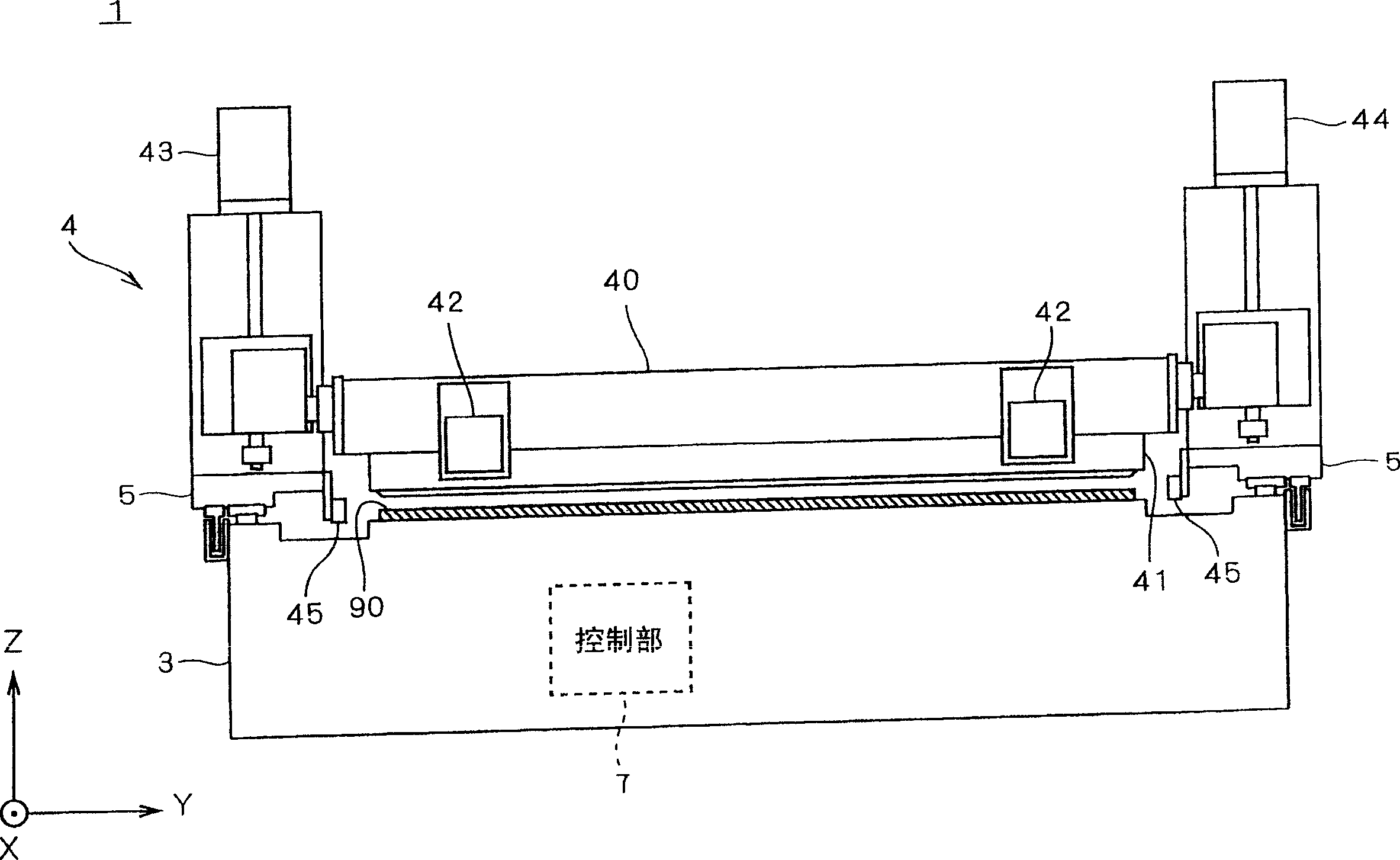
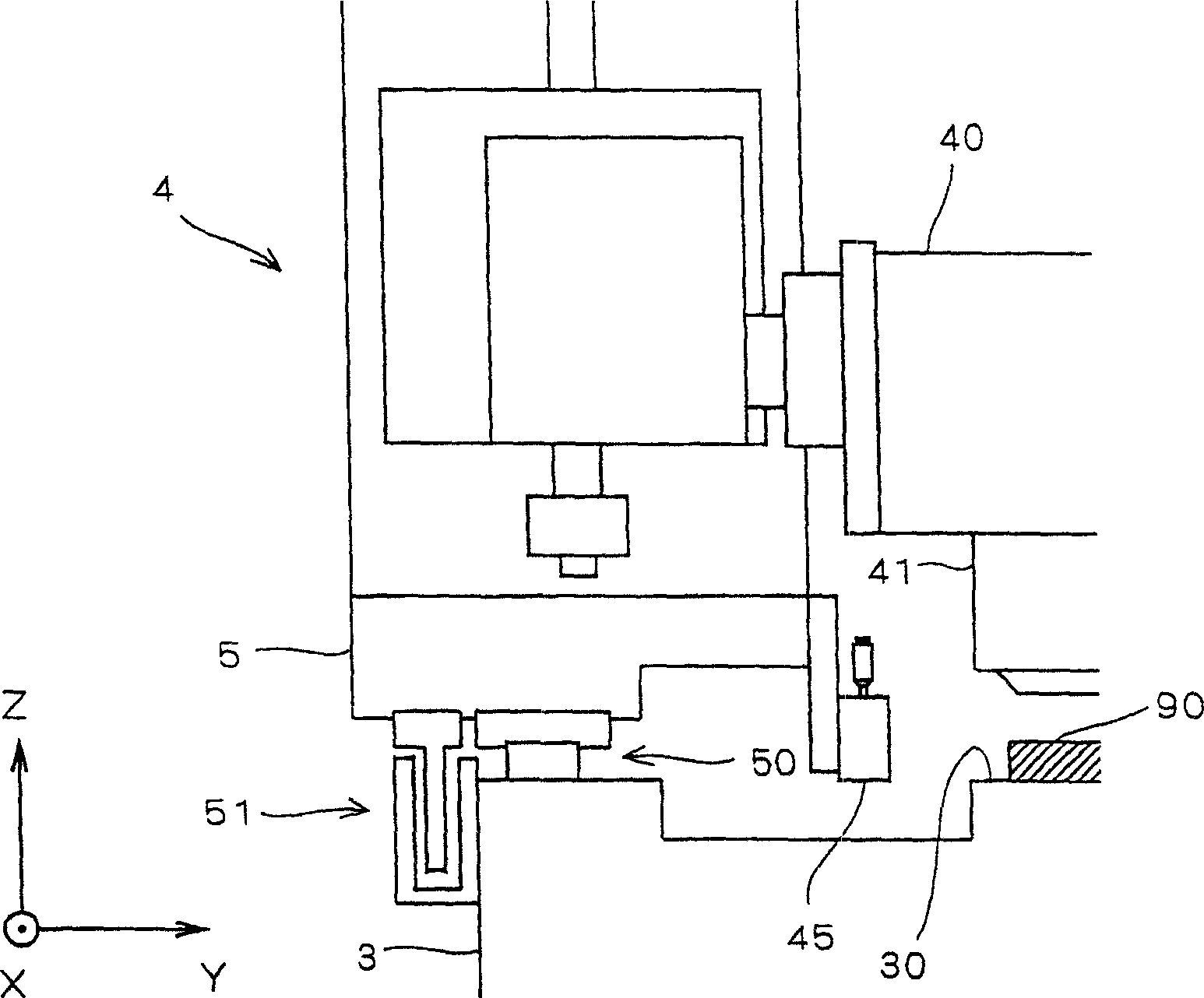
[0062] figure 1 It is a front view of the substrate processing apparatus 1 according to the first embodiment of the present invention. figure 2 It is an enlarged view of the peripheral portion of the detection sensor 45 of the substrate processing apparatus 1 . in addition, figure 1 and figure 2 Among them, for the convenience of illustration and description, it is defined that the Z-axis direction represents the vertical direction, and the XY plane represents the horizontal plane. They are defined for convenience in order to grasp the positional relationship, and are not limited to the directions described below. The following figure is also the same.

[0063] A square glass substrate used for manufacturing a screen panel of a liquid cr...


PUM


Abstract

To prevent the deterioration of the detection accuracy of an object which comes into contact with a slit nozzle. The substrate treating device is provided with detection sensors 450, 451, and 452 which detect the object which comes into contact with the slit nozzle. The laser light rays of the detection sensors 450, 451, and 452 are set so that the rays may be narrowed down at positions shifted in the Y-axis direction. In this way, the effective detecting ranges E1, E2, and E3 of the sensors 450, 451, and 452 inspect the scanning range E0 of the slit nozzle in a shared state. When the object is detected at one of the sensors 450, 451, and 452 on the basis of the detected results of the sensors 450, 451, and 452, the movement of the slit nozzle is stopped and a warning is displayed.

Description

technical field [0001] The present invention relates to a technique of a substrate processing apparatus that scans a substrate while ejecting a processing liquid from a nozzle to apply the processing liquid on the surface of the substrate. More specifically, it relates to a technology for detecting interference objects with high precision in order to prevent nozzles from being interfered by foreign objects (objects) during nozzle scanning. Background technique [0002] Coating equipment (substrate processing device). As a coating device, there are known slit coaters that perform slit coating with a slit nozzle with a slit-shaped discharge part, and slit spinners that perform spin coating after the aforementioned slit coating. applicator etc. [0003] Such a coating device applies the processing liquid by moving the slit nozzle or the substrate while the tip of the slit nozzle is brought close to the substrate. There are foreign objects in between, which will make the sub...

Claims


Application Information

Patent Timeline
Patent Type & Authority Applications(China)
IPC IPC(8): G03F7/16B05C5/02B05C11/00B05D3/00G02F1/13H01L21/027
CPCG02F1/1303G03F7/16H01L21/67259
Inventor 高木善则西冈贤太郎
Owner DAINIPPON SCREEN MTG CO LTD
Why Eureka
Try Eureka