
Process for producing resonant tag and resonant tag

A label and resonance technology, applied in the manufacture of resonance labels and the field of resonance labels, can solve the problems of disconnection, interconnection, bad circuits, etc.

Inactive Publication Date: 2005-01-12
NOVATRON ELECTRONICS HANGZHOU
View PDF1 Cites 3 Cited by
  • Summary
  • Abstract
  • Description
  • Claims
  • Application Information

AI Technical Summary

Problems solved by technology

[0020] Circuit-shaped coils are formed by etching metal foils such as aluminum foil and copper foil, or by coating conductive paint containing these metal powders. Sometimes disconnected or interconnected to create a bad circuit

Method used


Image

  • Process for producing resonant tag and resonant tag
  • Process for producing resonant tag and resonant tag
  • Process for producing resonant tag and resonant tag

Examples


Embodiment 1

[0066] Embodiments of the present invention will be described below with reference to the drawings, but the present invention is not limited to these examples.

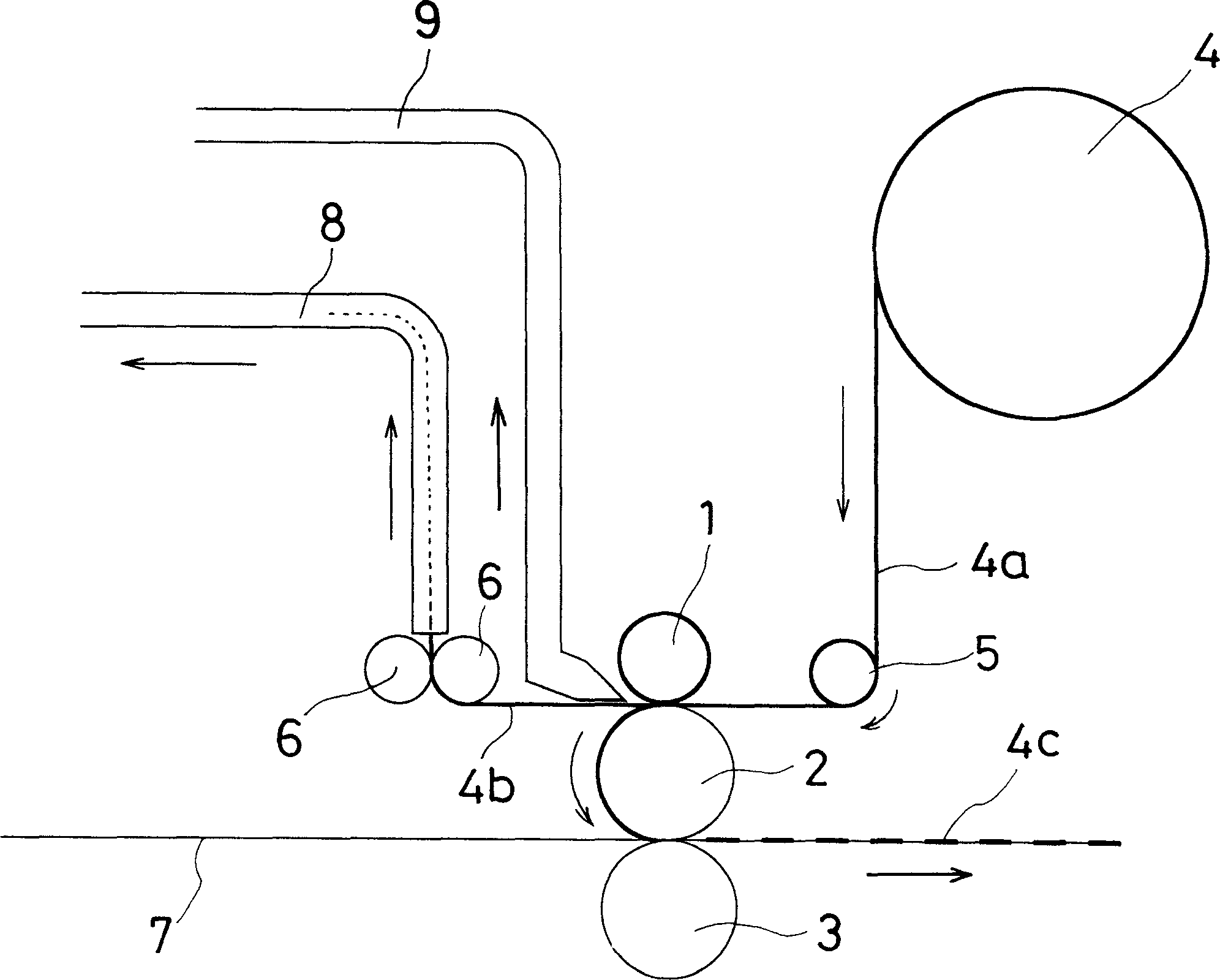
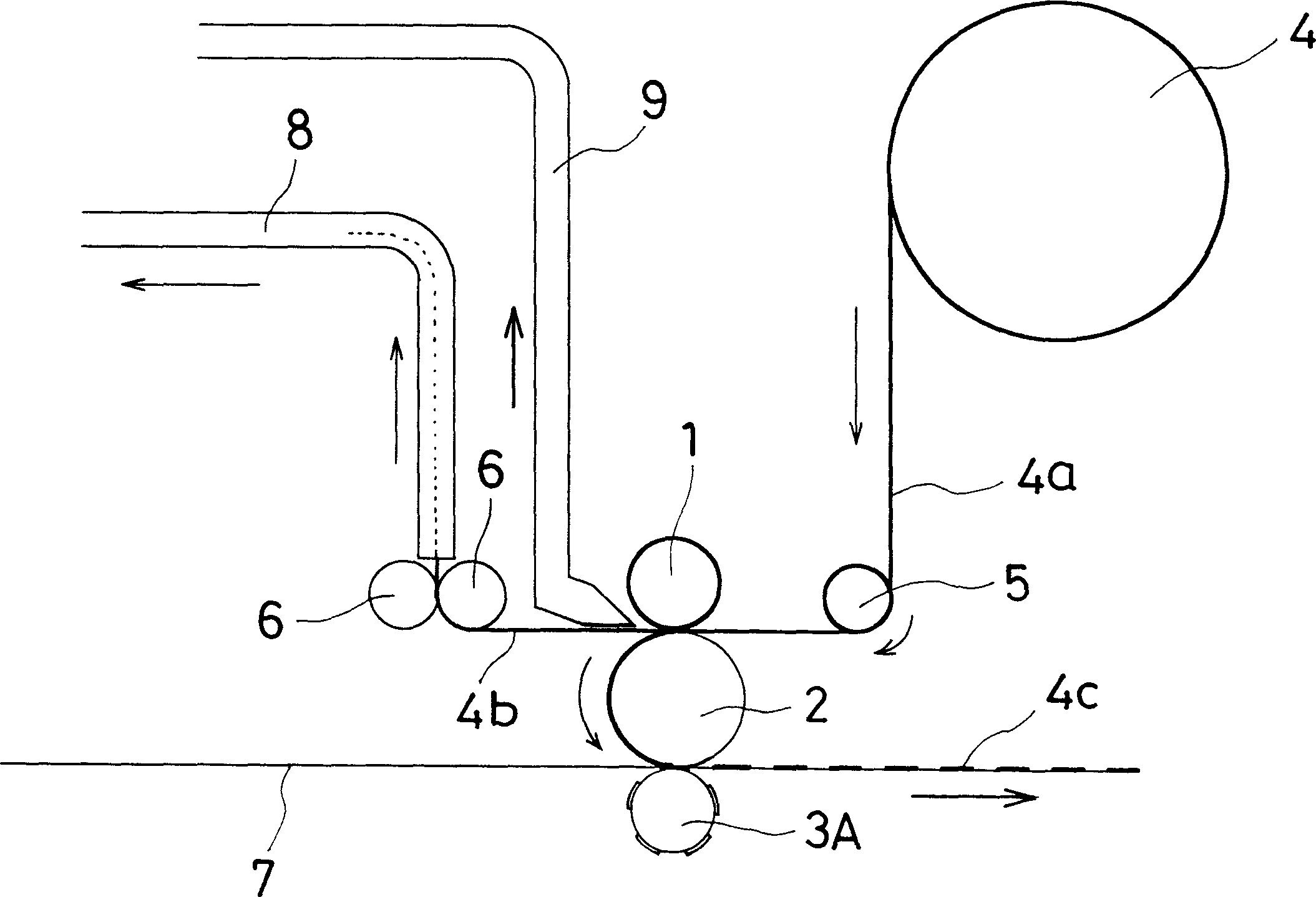
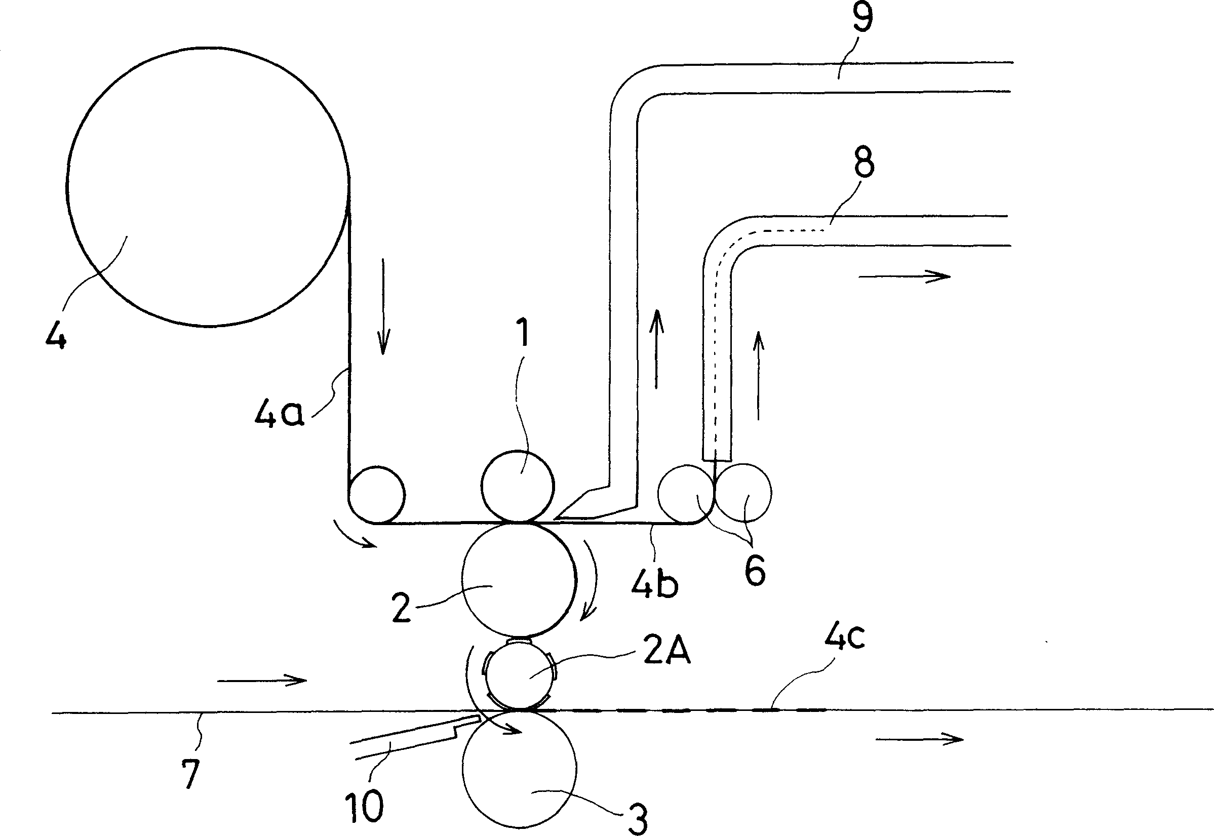
[0067] figure 1 It is a figure which shows an example of the basic method of this invention, 1 shows a die roll, 2 shows a transfer roll, and 3 shows a bonding roll. In practice, the metal foil 4a coated with a thermal adhesive resin is unwound from its roll 4, and fed between the die roll 1 and the transfer roll 2 via the guide roll 5 and punched into a predetermined shape. The die-cut metal foil 4c is held on the surface of the roller 2 by the suction hole (not shown) provided on the transfer roller 2, and sticks to the substrate flowing on the bonding roller 3 that is in contact with the lower side of the transfer roller 2. Sheet 7 on.

[0068] In the case of this example, the roller surfaces of the transfer roller 2 and the bonding roller 3 are flat, and the bonding roller 3 is a metal heating roller (heating r...

Embodiment 2

[0076] Embodiment 2 and comparative example

[0077] The size of the resonant tag: 40×40mm (the size of the circuit periphery)

[0078] Resonant frequency: 8.2MHz

[0079] Under the above conditions, a resonant tag of the present invention (Example) and a prior art resonant tag were produced and their performances were compared.

[0080] Embodiment is the resonant tag of the two-sided coil form shown in Fig. 4D, and comparative example is taken as Figure 7 in the form of a single-sided coil.

[0081] The composition and properties are shown in Table 1.

[0082] comparative example

Example

Coil

Material

Thickness (Front / Reverse)

Number of turns

Dielectric

capacitor

Area / capacity

L (inductance)

coil length

coil resistance

Q calculated value

measured value

aluminum

50μm / 10μm

8

20μm polyethylene film

121mm 2 / 128pF

3.06μH

980mm

0.6860Ω

230 ...


PUM

PropertyMeasurementUnit
resonanceaaaaaaaaaa
Resonant frequencyaaaaaaaaaa

Abstract

A process for producing a resonant tag, wherein a metal foil having a thermal adhesion adhesive applied to at least one face thereof is stamped out into a circuit-like shape and is adhered to a base sheet, the process comprising: stamping out the metal foil into a predetermined shaped metal foil portion (4c) while being passed through a die roll (1) having thereon a stamping blade with a predetermined shape and a transfer roll (2) in contact with the die roll (1) which functions also as a die back-up roll; holding this metal foil portion obtained by the stamping-out operation onto the surface of the transfer roll by suction holes formed in the transfer roll; and thermally adhering the stamped metal foil portion to the base sheet (7) in contact with the transfer roll (2) at its another face by an adhesive roll (3) in contact with the transfer roll through the base sheet.

Description

[0001] The patent application of the present invention is a divisional application of the invention patent application with the application number 99118842.X, the application date was September 15, 1999, and the invention name is "manufacturing method of resonant tag and resonant tag". technical field [0002] The present invention relates to a method of manufacturing a resonant tag or the like having a circuit that resonates with radio waves of a specific frequency emitted from a detection device. Background technique [0003] As already known, a resonant tag is a tag that has a circuit that resonates with radio waves of a specific frequency. As long as this resonant tag exists in the area that emits radio waves of a specific frequency, the buzzer of the detection device can be resonated. or the warning light works. Therefore, in department stores, discount stores, video rental stores, CD stores, etc., this resonant tag is mounted on merchandise and the like to prevent thef...

Claims


Application Information

Patent Timeline
Patent Type & Authority Applications(China)
IPC IPC(8): G06K19/077G08B13/24H01F5/00H01F41/04H05K3/04
CPCG08B13/242G08B13/2431G08B13/244G08B13/2437G06K19/07749H01F5/003G06K19/07718H01F41/041H05K3/041
Inventor 内堀晋弥畑中芳纪水川贵章
Owner NOVATRON ELECTRONICS HANGZHOU
Learn More