Filter for cell
A cell filter, cell technology, applied in the direction of blood filtration, tissue cell/virus culture devices, biochemical instruments, etc., to achieve the effect of improving filtration efficiency, easy installation and portability, and small size
- Summary
- Abstract
- Description
- Claims
- Application Information
AI Technical Summary
Problems solved by technology
Method used
Image

Examples
Embodiment 1
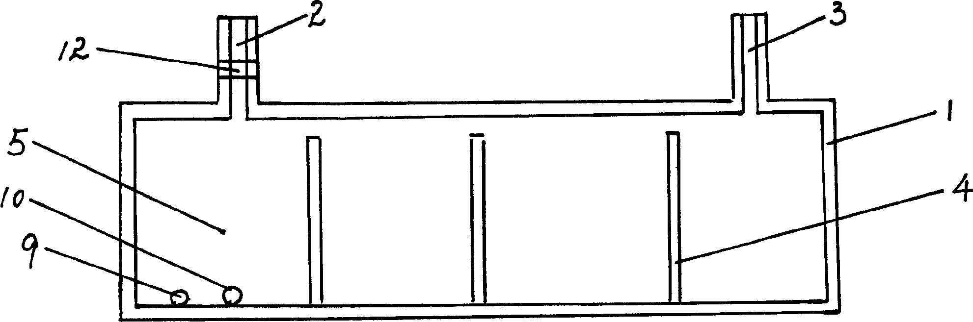
[0037] Prepare a layer of light-sensitive material on substrate materials such as silicon wafers, glass, ceramics, or metals, perform optical exposure according to the designed microstructure photomask, and form concave-convex results of light-sensitive materials on the substrate after development. Various microfluidic structures are prepared on the substrate by wet etching or dry etching, such as input and output channel ports, fluid blocking structures, fluid pools, fluid channels, etc. After completing the preparation of various structures, the devices prepared above are packaged with silicon wafers, glass plates, plastics, metal or ceramic plates. The surfaces of the above-mentioned materials are treated before or during use to make them biocompatible and not harmful to living organisms. After the device is packaged, the surface of the material inside the device is chemically treated to make it anti-coagulant.
Embodiment 2
[0039] Prepare a layer of light-sensitive material on substrate materials such as silicon wafers, glass, ceramics, or metals, perform optical exposure according to the designed microstructure photomask, and form concave-convex results of light-sensitive materials on the substrate after development. A layer of polymerizable polymer material (such as plastic, rubber, etc.) is coated on the above-mentioned concave-convex structure. After the polymer material is solidified, it is separated from the substrate, and various microfluidic structures are prepared on the surface of the polymer material, such as input and output channel ports, fluid blocking structures, fluid pools, fluid channels, etc. After completing the preparation of various structures, the devices prepared above are packaged with silicon wafers, glass plates, metal, plastic, rubber or ceramic plates. The surfaces of the above-mentioned silicon wafers, glass, ceramics, plastics or metals are treated before or during ...
Embodiment 3
[0041] According to the designed microstructure, the corresponding plastic or rubber precision molds are prepared. Direct application of micro-casting technology to prepare various plastic or rubber microfluidic structures, such as input and output channel ports, fluid blocking structures, fluid pools, fluid channels, etc. Epithelial cell antibodies are immobilized on the surface of the fluid pool to capture tumor cells. After the preparation of various structures is completed, assembly and packaging are carried out, and the materials used should be non-biologically toxic materials. After the device is packaged, the surface of the material inside the device is chemically treated to make it anti-coagulant.
PUM
 Abstract
Description
Claims
Application Information
 - R&D
- Intellectual Property
- Life Sciences
- Materials
- Tech Scout
- Unparalleled Data Quality
- Higher Quality Content
- 60% Fewer Hallucinations
Browse by: Latest US Patents, China's latest patents, Technical Efficacy Thesaurus, Application Domain, Technology Topic, Popular Technical Reports.
© 2025 PatSnap. All rights reserved.Legal|Privacy policy|Modern Slavery Act Transparency Statement|Sitemap|About US| Contact US: help@patsnap.com