Method of manufacturing a matrix for a cathode-ray tube (CRT)

A substrate and electrode technology, applied in cathode ray tube/electron beam tube, cold cathode manufacturing, electrode system manufacturing, etc., can solve problems such as different sizes, misalignment, and inability to realize porous baffles

Inactive Publication Date: 2004-12-29
THOMSON LICENSING SA
View PDF2 Cites 0 Cited by
  • Summary
  • Abstract
  • Description
  • Claims
  • Application Information

AI Technical Summary

Problems solved by technology

However, with conventional substrate processing such as those described in U.S. Patent No. 3,558,310, formation of substrate lines using a porous mask having a transmittance of about 30% to about 80% cannot be achieved because the light image projected therefrom overlap each other such that the positions of such stromal lines are misaligned on the screen surface and have different sizes

Method used


Image

  • Method of manufacturing a matrix for a cathode-ray tube (CRT)
  • Method of manufacturing a matrix for a cathode-ray tube (CRT)
  • Method of manufacturing a matrix for a cathode-ray tube (CRT)

Examples


Embodiment Construction

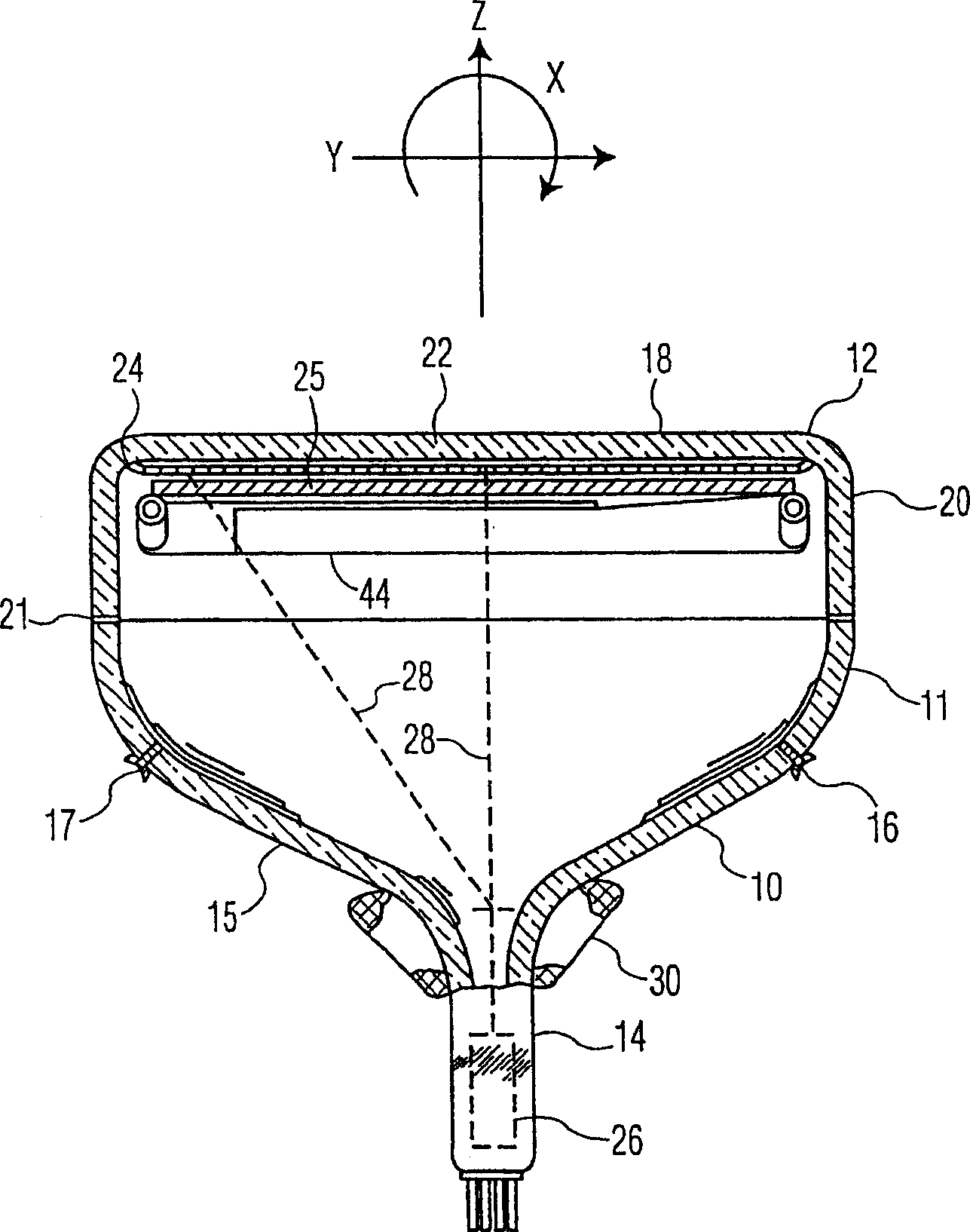
[0024] figure 1 A color cathode ray tube (CRT) 10 is shown having a glass envelope 11 comprising a face plate 12 and a neck 14 joined by a funnel 15 . The funnel 15 has an internal conductive coating (not shown) that contacts the anode button 16 and extends from the anode button 16 to the neck 14 .

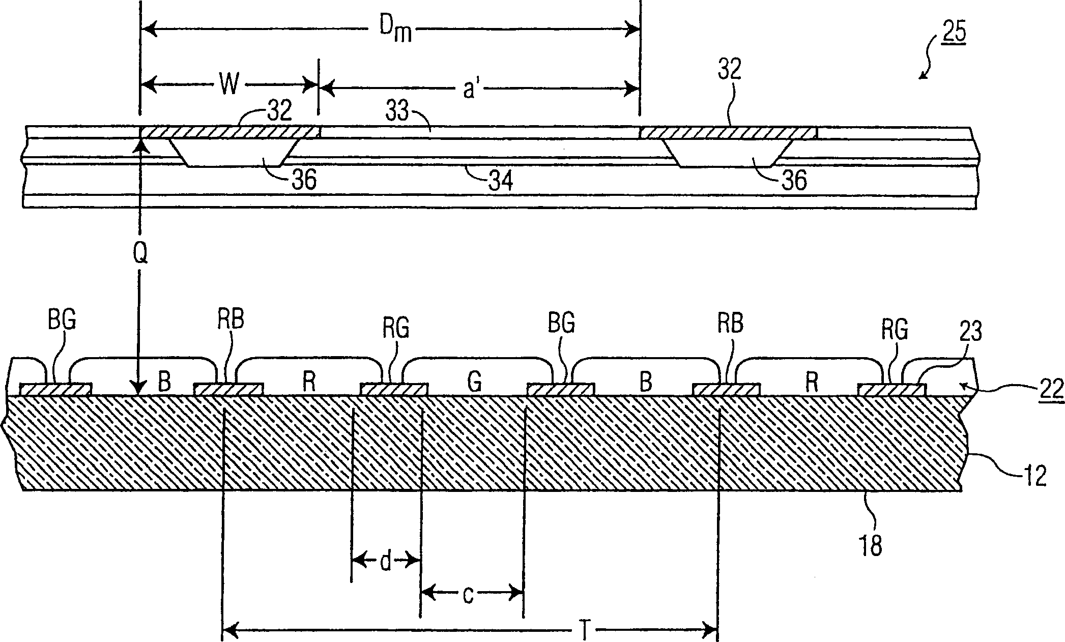
[0025] Panel 12 includes a viewing panel 18 and a peripheral flange or side wall 20 sealed to funnel 15 by glass frit 21 . On the inner surface of the viewing panel 18 is carried a three-color fluorescent screen 22 . Such as figure 2 The screen 22 shown in cross-section in is a line screen, which includes a plurality of screen elements including red, green and blue fluorescent strips R, G and B arranged in triplets, respectively, Each triplet includes fluorescent lines for each of the three colors. The R, G and B fluorescent stripes are usually printed in a vertical direction.

[0026] Such as figure 2 The light absorbing matrix 23 is shown separating the fluorescent lines...


PUM


Abstract

A method of manufacturing a luminescent screen assembly, having a light-absorbing matrix with a plurality of substantially equally-sized openings therein, on an inner surface of a faceplate panel of a cathode-ray tube (CRT) is provided. The tube has a color selection electrode spaced from the inner surface of the faceplate panel in which the color selection electrode has a plurality of strands interleaved with slots. The method includes the steps of providing a first photoresist layer, whose solubility is altered when exposed to light, such that greater dosages of light reduce the solubility thereof. The first photoresist layer is applied to the inner surface of the faceplate panel. The first photoresist layer is exposed to light from a light source, located relative to a central source position, as well as two symmetrical source positions relative to the central source position. The exposure selectively alters the solubility of the illuminated areas of the first photoresist layer to produce therein regions with greater solubility and regions of lesser solubility. The regions of greater solubility are subsequently removed to uncover areas of the inner surface of the faceplate panel, while retaining the regions of lesser solubility. The inner surface of the faceplate panel and the retained regions are then overcoated with a light-absorbing material. Thereafter, the retained regions of the first photoresist layer and the light-absorbing material thereon are removed, uncovering portions of the faceplate panel and defining first guardbands of light-absorbing material on the inner surface of the faceplate panel. This photolithographic process is repeated with a second photoresist layer and a third photoresist layer to define second guardbands of light-absorbing material and third guardbands of light-absorbing material, respectively.

Description

technical field [0001] The present invention relates to a color cathode ray tube (CRT), and more particularly to a color CRT including a fluorescent screen assembly. Background technique [0002] A color cathode ray tube (CRT) generally includes an electron gun, a perforated mask and a screen. The porous mask is inserted between the electron gun and the screen. The screen is located on the inner surface of the panel of the CRT tube. The porous mask is used to direct the electron beams generated in the electron gun to the appropriate colored light emitting phosphors on the screen of the CRT tube. [0003] The screen may be a fluorescent screen. Phosphor screens typically include an array of three different colored light-emitting phosphors (eg, green, blue and red). Each color-emitting phosphor is separated from each other by a matrix line. The matrix wires are formed from a light absorbing black inert material. [0004] The matrix lines can be deposited on the screen us...

Claims


Application Information

Patent Timeline
IPC IPC(8): H01J9/227H01J29/32
CPCH01J29/327H01J9/2278H01J9/227
Inventor 塞缪尔·珀尔曼罗伯特·E·克雷德小理查德·莱普拉塔
Owner THOMSON LICENSING SA
Why Eureka
Try Eureka