Dynamic calcinator for inorganic material

A technology of dynamic calcination and inorganic materials, applied in furnaces, muffle furnaces, cooking furnaces, etc., can solve the problem that horizontal or vertical multi-stage fluidized calcination furnaces have not been widely used, cannot meet high-strength turning, and product quality is difficult Guarantee and other issues, to achieve the effect of solving fluidization quality problems, improving reliability, and uniform residence time

Inactive Publication Date: 2004-12-29
TAIYUAN UNIV OF TECH
View PDF0 Cites 2 Cited by
  • Summary
  • Abstract
  • Description
  • Claims
  • Application Information

AI Technical Summary

Problems solved by technology

The fluidized calcination furnace shows relatively high unit production capacity and relatively good temperature uniformity, but the fluidized process itself belongs to a fully mixed reactor, and the residence time distribution of the material is very wide, so it is difficult to ensure that the product has the same residence time For this reason, batch production has to be adopted to meet the requirement of uniform material residence time
Some have developed horizontal or vertical multi-stage fluidized calciners to overcome the shortcomings of non-uniform material residence time. However, due to the problem of material transfer between stages and the technical problems of fluidized air distribution plates in large fluidized beds, horizontal Or vertical multi-stage fluidized calciner has not been widely used
The vertical multi-stage agitation calciner has been used in the light calcination of refractory materials or kaolin calcination, but the calcination chambers at all levels of this calcination furnace share the same stirring shaft, and the material flow between each chamber is only dependent on the drop, without other control measures. Therefore, it cannot meet the requirements of some calcination processes (such as coal series kaolin calcination) for dynamic calcination chambers with different turbulence intensities at all levels, and because the material flow velocity is related to the agitation velocity, it cannot meet the requirements of long residence time and high intensity turbulence. Require
In the continuous production of materials, it is often difficult to guarantee the product quality due to the uneven residence time and temperature of the materials in the calciner. At the same time, the thermal efficiency is low because the materials and the calciner are indirectly heated.

Method used


Image

  • Dynamic calcinator for inorganic material
  • Dynamic calcinator for inorganic material

Examples


Embodiment Construction

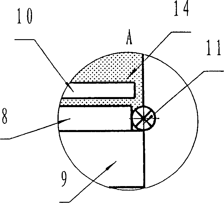
[0019] The present invention is described as follows in conjunction with accompanying drawing by embodiment:

[0020] figure 1 It is a structural representation of the present invention.

[0021] As shown in the figure, the shell 1, the heat insulation layer 2 and the refractory lining 3 constitute the furnace body. There are feeding ports 4 and smoke exhaust outlets 5 on the upper part of the furnace body and on one side of the furnace body. On the other side of the furnace body lower part There is a discharge port 6 on one side, and a burner nozzle 7 is arranged above the discharge port 6, and a burner nozzle 7 is fixed between one side of the furnace body and the other side of the furnace body, the discharge port 6 and the burner nozzle 7 below the feed port 4. Step-shaped gas distribution plate 8, a fluidized air distribution chamber 9 is fixed below the gas distribution plate 8, an agitator 10 is installed on the gas distribution plate 8, and an impeller feeder 11 is ins...


PUM


Abstract

The dynamic inorganic material calcining furnace has one furnace body comprising outer casing, heat insulating layer and refractory material. The furnace body has feeding port and fume exhausting port on one side in the upper part, discharge port and burner nozzle on the other side in the lower part, gas distributing plates with fluidized air distributing chamber and stirrer on two sides, material lowering vane wheel device between the gas distributing plates, main fluidized air distributing pipe in the bottom, and fluidized air distributing branches in the luidized air distributing chamber and the main fluidized air distributing pipe. The present invention has the advantages of low cost, high heat efficiency, homogeneous calcined material staying time, homogeneous temperature and stable product quality.

Description

technical field [0001] The invention belongs to a calciner for inorganic non-metallic materials, in particular to a dynamic calciner for powder or granular inorganic non-metallic materials. Background technique [0002] Dynamic calcining powder furnace refers to thermal equipment that heats powder materials in a moving state (turning, stirring or suspension state) by means of pneumatic, electric or mechanical force. This is a type of thermal equipment that has long been recognized as an effective treatment of inorganic powder materials. At present, such equipment has been widely used in cement, power generation, chemical, refractory and other industries. Typical dynamic calcination equipment includes rotary kiln, fluidized calcination furnace, vertical multi-stage agitation calcination furnace, etc. Dynamic calcination equipment solves the problem of material temperature uniformity, and at the same time, it also shows excellent performance that static calcination equipment ...

Claims


Application Information

Patent Timeline
Patent Type & Authority Applications(China)
IPC IPC(8): F27B5/02
Inventor 高峰胡雅琴李允梅
Owner TAIYUAN UNIV OF TECH
Why Eureka
Try Eureka