
Pitch diameter displaced screw

A thread and displacement technology, applied in the direction of threaded fasteners, nuts, bolts, etc., can solve the problems of strong pressure resistance and weak tensile force of threads

Active Publication Date: 2004-11-03
杉村宣行
View PDF1 Cites 6 Cited by
  • Summary
  • Abstract
  • Description
  • Claims
  • Application Information

AI Technical Summary

Problems solved by technology

[0006] However, due to the characteristics of strong pressure resistance and weak tensile strength of the thread, when the same force is applied to the thread teeth 4 and 14 of the aforementioned two threads, the thread on the side subjected to the tensile stress, that is, the internal thread 1 starts from the thread 1 first. Root 5 begins to fail

Method used


Image

  • Pitch diameter displaced screw
  • Pitch diameter displaced screw
  • Pitch diameter displaced screw

Examples


experiment example

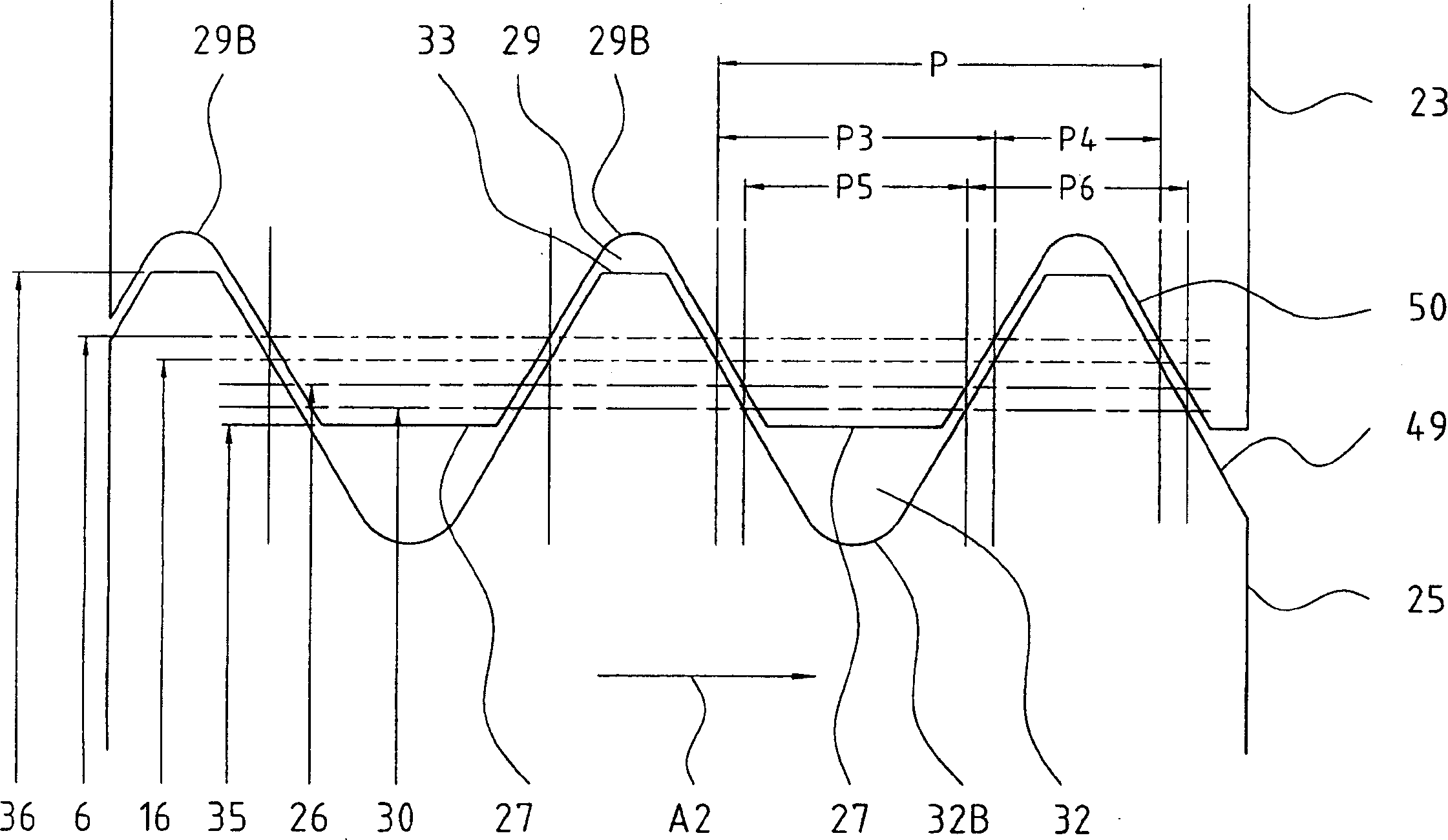
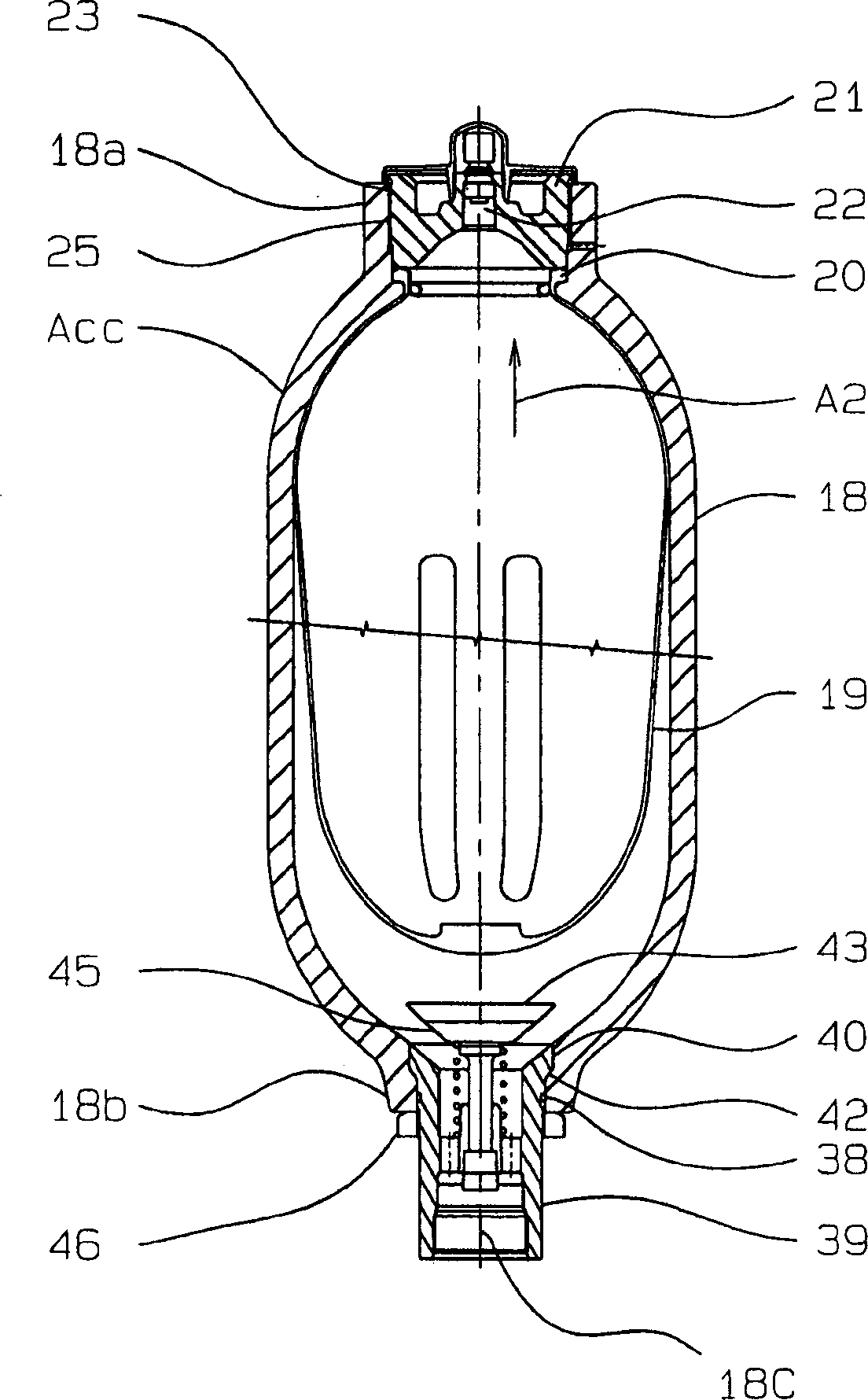
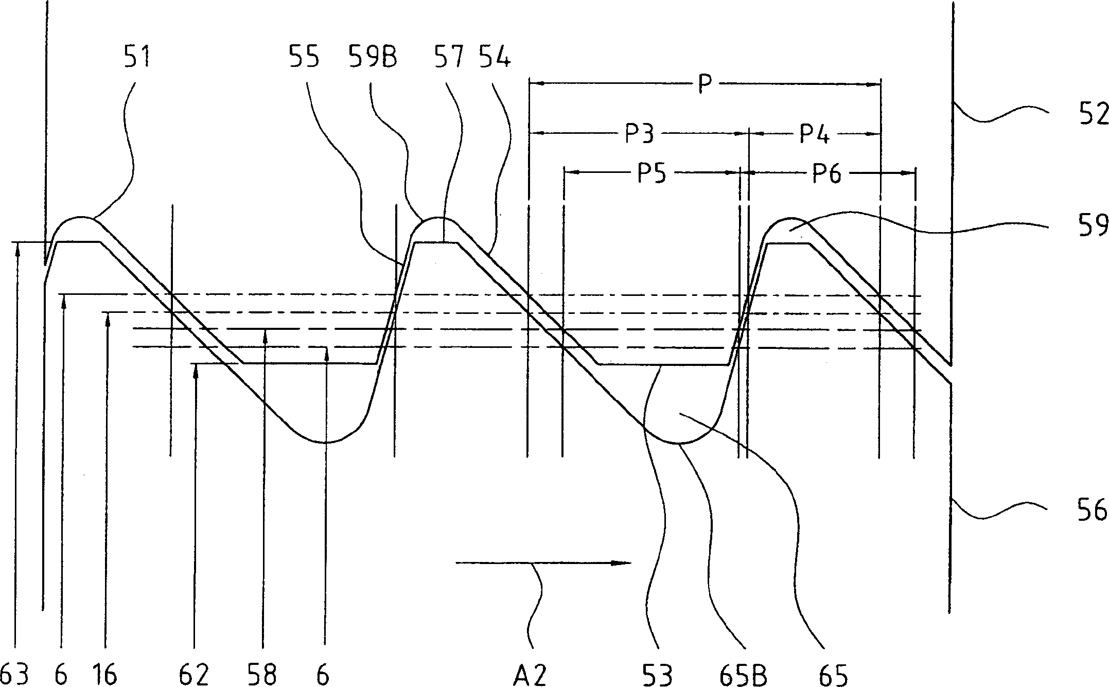
[0032] The present inventor uses the pressure accumulator (Nippon Accumulator Co., Ltd. (Nippon Akuumureta Co., Ltd.), model N210-1D) of the aforementioned first and second embodiments and the conventional example, and uses the finite element method to analyze the inner thread. The tensile stress value of the first thread root was analyzed, and the following results were obtained. Wherein, the aforementioned first thread root refers to the first thread root at the root of the internal thread that bears the load of the external thread first.

[0033] ·Existing example of metric internal thread (see Figure 4 ): 780N / mm 2

[0034] The metric internal thread of the present invention (see figure 1 ): 570N / mm 2

[0035] ·The inverted serrated internal thread of the existing example (see Figure 5 ): 592N / mm 2

[0036] ·The inverted sawtooth internal thread of the present invention (see image 3 ): 490N / mm 2

[0037] The above results clearly show that, for the metric int...


PUM


Abstract

As to a weaker screw between the internal screw and the external screw, the width of a thread ridge of an internal screw and an external screw which mutually mesh in the position of its standard pitch diameter is formed greater than a width of a thread groove of a mating screw.

Description

technical field [0001] The present invention relates to a thread for accumulators, etc., and more particularly to a pitch diameter displacement thread in which the thread strength of the weaker one of mutually screwed external threads and internal threads is improved. technical background [0002] Conventionally, triangular threads such as metric threads and inverted serrated threads have been used for pressure accumulators and the like. Standard triangular thread such as Figure 4 As shown, the cross-sectional shape of the thread teeth is roughly formed as an equilateral triangle; in addition, as Figure 5 As shown, the inclination angle of the thread tooth side of the standard inverted serrated thread is formed in this way: the side inclination angle of the thread tooth is opposite to the side inclination angle of the thread tooth of the sawtooth thread, that is, the pressure side inclination angle is greater than the gap side inclination angle (refer to Japan Shi Kaiping ...

Claims


Application Information

Patent Timeline
Patent Type & Authority Applications(China)
IPC IPC(8): F16B33/02F16B33/04
CPCF16B33/02
Inventor 杉村宣行
Owner 杉村宣行
Learn More