Two stroke engine

An engine, two-stroke technology, applied in the direction of engine components, engine control, combustion engine, etc., to achieve the effect of high sealing, simple assembly, and small weight

Active Publication Date: 2004-10-06
ANDREAS STIHL AG & CO KG
View PDF1 Cites 3 Cited by
  • Summary
  • Abstract
  • Description
  • Claims
  • Application Information

AI Technical Summary

Problems solved by technology

Simple production of the cylinder by die-casting is not possible due to the branching of the air ducts

Method used


Image

  • Two stroke engine
  • Two stroke engine
  • Two stroke engine

Examples


Embodiment Construction

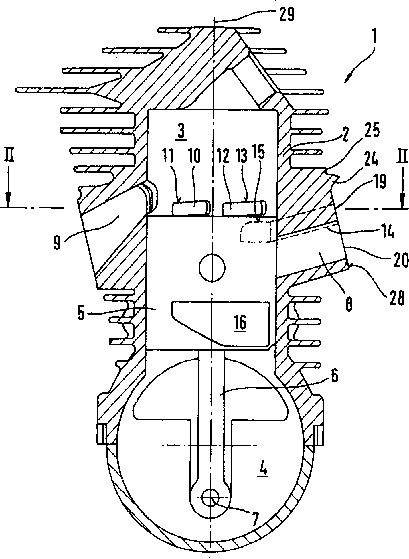
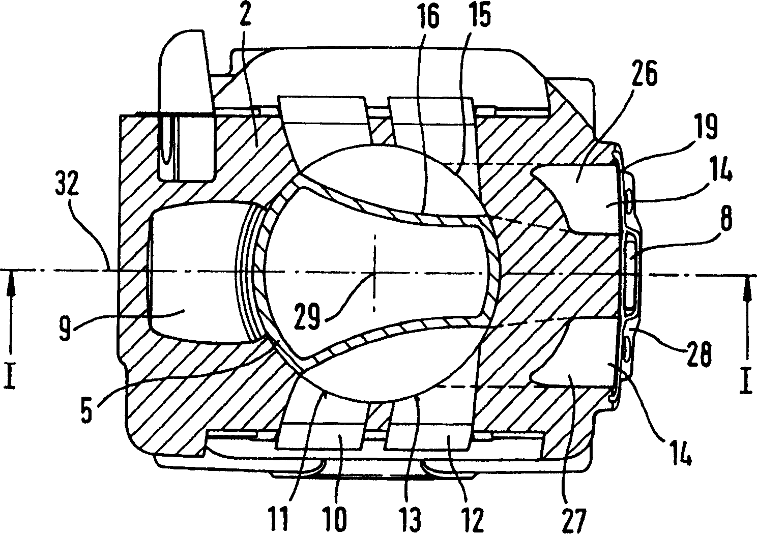
[0022] exist figure 1 and 2 The illustrated two-stroke engine 1 comprises a cylinder 2 in which a combustion chamber 3 is located. As shown in Figure 4, the combustion chamber 3 is defined by a piston 5 which moves up and down. The piston 5 is driven by the crank connecting rod 6 and is supported in the crankcase 4 figure 1 The crankshaft 7 is shown. The combustion chamber 3 has an exhaust gas outlet 9 outwards. at the predetermined position of the piston, e.g. figure 1 In the piston position shown in , the crankcase 4 is connected to the combustion chamber 3 via the overflow pipe grooves 10 and 12 . The overflow pipe groove 10 close to the exhaust port leads to the combustion chamber 3 through an overflow window 11 here, and the overflow pipe groove 12 far away from the exhaust port leads to the combustion chamber through an overflow window 13 . The cylinder 2 has a center plane 32 which roughly divides the exhaust port in the middle and which includes the cylinder long...


PUM


Abstract

A two-cycle engine is provided and includes a cylinder in which is formed a combustion chamber delimited by a reciprocating piston that via a connecting rod drives a crankshaft rotatably mounted in a crankcase that, in predetermined positions of the piston, communicates with the combustion chamber via transfer channels. The cylinder has an outlet from the combustion chamber. An intake duct leads into the crankcase for a supply of fuel, and an air duct supplies substantially fuel-free air. In the vicinity of the piston the air duct is divided into two branches that open out at air openings of a connecting flange formed on the cylinder. A cover is disposed on the connecting flange and extends over the air openings. A flow divider on the connecting flange projects beyond a plane thereof and into the cover. The flow divider divides an air flow in the air duct to the two branches.

Description

technical field [0001] The invention relates to a two-stroke engine of the type stated in the preamble of claim 1, in particular for use in a hand-guided tool such as a chainsaw, cutting machine or the like. Background technique [0002] A two-stroke engine is known from WO 00 / 43660, in which the air channel is divided into two branches. The two branches of the air channel lead to a common connecting flange. The air channel is divided into two branches in the airflow direction behind the connecting flange by a partition wall. Here, the two branches of the air channel diverge from each other as seen from the connecting flange. Due to the branching course of the air channel, simple production of the cylinder by die-casting is not possible. Contents of the invention [0003] The object of the present invention is to provide a two-stroke engine of the type mentioned at the outset, which can be easily produced by die-casting and has small structural dimensions. [0004] Thi...

Claims


Application Information

Patent Timeline
Patent Type & Authority Applications(China)
IPC IPC(8): F02B25/14F02B25/22F02B33/04F02B63/02F02B75/02F02F1/22F02F3/24
CPCF02B25/14F02B25/22F02B33/04F02B2075/025
Inventor H·阿门德K·M·乌尔
Owner ANDREAS STIHL AG & CO KG
Why Eureka
Try Eureka