Working device and working method, and production equipment using it
A processing device and processing method technology, applied in the direction of metal processing equipment, electric heating devices, welding equipment, etc., can solve the problems of inability to perform high-speed solder joints, solder balls or solder scattering, etc.
- Summary
- Abstract
- Description
- Claims
- Application Information
AI Technical Summary
Problems solved by technology
Method used
Image

Examples
Embodiment approach 1
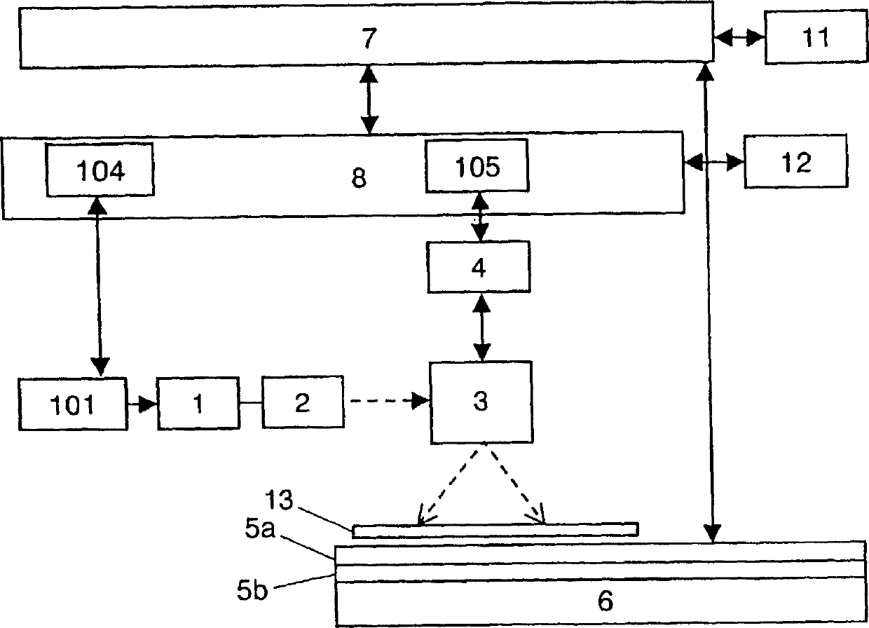
[0047] FIG. 1 is an overall configuration diagram of a processing apparatus in the first embodiment. The workpiece 13 is composed of a printed circuit board coated with cream solder as a bonding agent, and a surface mount component fixed to the substrate. In order to solder and join printed substrates and surface mount components, the device includes: a light energy power supply 101 and a laser diode device 1 that irradiate light energy to melt solder, and an optical system 2 that guides light energy to the joint position as an optical means for irradiating spot light , the current control device 4 and the current mirror 3 for scanning the spot light at a high speed on the part to be fused, and the table 5 a on which the workpiece 13 is placed. The apparatus also includes a heating device 5b for preheating the workpiece 13 on the table 5a as means for improving the processing quality and performance.
[0048] The workpiece 13 is placed on the table 5a and heated by a heating ...
Embodiment approach 2
[0054] After the control device 8 of Fig. 1 reads out the processing condition corresponding to the processing position of the processed object 13 from the processing condition memory 104, it supplies the light energy power supply 101, and the power supply 101 controls the laser diode device 1 to make it generate specified energy, so that by The light converged by the optical system 2 is reflected by the galvano mirror 3 and then irradiates the workpiece 13 . At the same time, by supplying the heating position information from the heating position memory 105 to the current control device 4, the current mirror can guide the incident light to the heating position. In addition, the heating device 5 b preheats the workpiece 13 based on information from the processing condition memory 104 .
[0055] A personal computer, a programmer, etc. are used as processing conditions 104, 105.
Embodiment approach 3
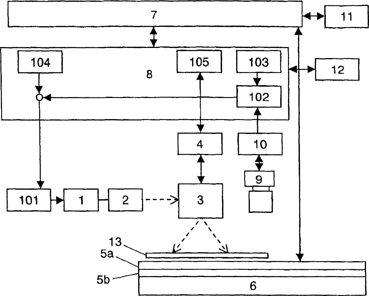
[0057] After the control device 8 in FIG. 2 reads out the corresponding current processing conditions from the processing condition memory 104 , it supplies the light energy power source 101 to process the workpiece 13 . At the same time, the processing state is read in by the camera 9, and the processing result is recognized by the image recognition device 10. The comparison means 102 compares the normal processing information stored in the processing state memory 103 with the recognized processing results, and then feeds back to the processing condition memory 104, and supplies the processing conditions corrected according to the feedback information to the optical power source 101 for welding and bonding.
PUM
 Abstract
Description
Claims
Application Information
 - R&D
- Intellectual Property
- Life Sciences
- Materials
- Tech Scout
- Unparalleled Data Quality
- Higher Quality Content
- 60% Fewer Hallucinations
Browse by: Latest US Patents, China's latest patents, Technical Efficacy Thesaurus, Application Domain, Technology Topic, Popular Technical Reports.
© 2025 PatSnap. All rights reserved.Legal|Privacy policy|Modern Slavery Act Transparency Statement|Sitemap|About US| Contact US: help@patsnap.com