[0011] The stator part of the known motor or generator uses a thicker wire
diameter circular coil to arrange multi-layer winding in the wire slot seat due to the need for a high-current
working environment (as shown in Figure 3A to Figure 3H As shown), even if the whole row of wires is used, but because the diameters of the round wires are different in size, the occupation ratios of various round wire diameters in the same wire slot seat are also different, and at the same time, it is not possible to uniformly arrange the wires in the same wire slot seat. The number of turns of various coils is arranged with various circular wire diameters in the way of occupation rate (as shown in Figure 3A-Figure 3G); the reasons mentioned above cause the speed design of the operating range of the motor or generator to occur greatly. troubled
[0012] Furthermore, as shown in accompanying drawings 1A-1H and Fig. 2A-C, U.S. Patent No. US5866965 discloses a kind of "variable reluctance-motorhaving foil wire wound coils with
metal foil coils", wherein, the patent The content is to provide a
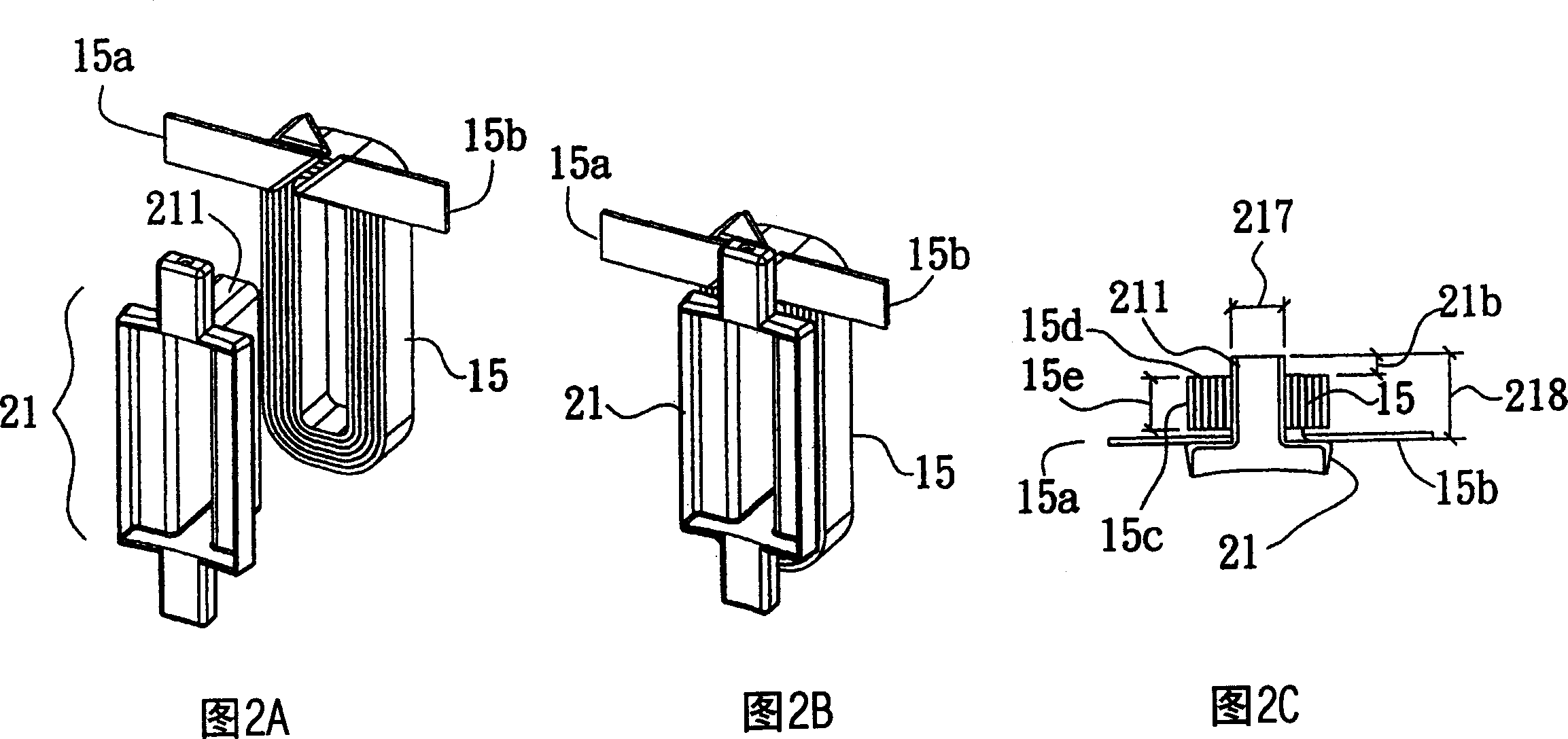
metal sheet coil (foil wire wound coil s) 15, that is, it is not used in a
working environment with a large current. The coil 15 is mainly wound by a drum
winding machine and sleeved on the
stator poles ) 13, the sheet
metal also has a corresponding face, a corresponding edge, a wire head end 15b and a wire
tail end 15a; but the face is sleeved on the surface of the
stator coil column (statorpoles) 13, and the two sides One of the parts is arranged on the bottom side (flat) 13a, and if so, the thread end 15b is embedded in the interior of the
metal sheet wound into a coil (as shown in Figure 2A-2C), so it is bound to be subjected to secondary
processing to lead out the thread End 15b (as shown in Figure 1A-1H) the "thread head end" of this sheet metal coil 15 must utilize three folds to turn the way and just can draw out, and its process is as shown in Figure 1A-1H, just can this thread head end 15b and the wire
tail end 15a is drawn to the outside, thus resulting in the absence of difficult
processing and wasteful
processing costs. Figure 1H can be compared to the coil 15 in the first figure of the US5866965 patent;
[0013] In addition, if the motor of this patent is to be applied to
high current occasions, it means that the coil must have a large cross-sectional area, that is, the thickness of the edge of the flat wire to be used must be thicker, based on the three folds of the patent The steering method is bound to be quite difficult in terms of
manufacturing engineering technology, because the thread end of the thicker and harder
metal sheet is not easy to lead out through multiple folds (as shown in Figure 1A-Figure 1D), so this patent case is difficult. For
high current applications
[0014] Also, the width of the surface of the
metal sheet must be slightly smaller than the width of the
stator poles 13, otherwise the wire head 15b of the patent case must not be able to be folded three times and turned to lead out (please refer to Figs. 1A-1B);
[0015] At the same time, the coil 15 of the patent US5866965 is applied to the
stator coil column 13 of the variable
reluctance motor stator part 11. The width is greater than the depth (as shown in the fourth figure of the patent), so the coil 15 can still obtain a reasonable However, when the coil manufacturing method of this patent is applied to the stator part of this
patent application, the reduction of its occupation rate and the flat coil can be explained by referring to Figure 2A to Figure 2C of this
patent application. The reason for the
thinning, the coil 15 is that the coil 15 of Fig. 1G is sleeved to the longitudinal vertical column end 211 of the slot seat 21 of Fig. 2, because the depth 218 of the vertical column end 211 is greater than the width 217, and the surface width 15e of the coil 15 Must not be greater than the width 217 of the vertical column end 211 (otherwise the thread end 15b cannot be folded and drawn out), so the occupation rate of its coil wire slot seat will be limited, as Figures 5A-5C It is the sectional view of the occupation ratio of the wire slot seat 21 of the patent US5866965 coil 15, the
circular coil 311 and the coil 31 of this
patent application respectively, so as Figure 5A Shown this patent case US5866965 its coil 15 occupation rate will be far lower than as Figure 5C The slot seat occupation ratio of the coil 31 of this patent application, meanwhile, the thickness of the side portion 15d is also much lower than the side portion 315 of the coil 31 of FIG. 4
[0016] The reduction of the above-mentioned coil
area ratio will lead to an increase in the impedance value of the
copper wire, which will increase the
power loss of the
copper wire in the coil and cause the high temperature phenomenon when the
copper wire is working. The impedance value of the
copper wire is proportional to the
working temperature of the
copper wire. The
working temperature The impedance of the
copper wire increases in direct proportion, so fully increasing the occupation rate of the coil in the wire slot can reduce the impedance of the copper wire. The above is very important in terms of high operating efficiency motors or generators.

