
Method for producing bonding wafer

A technology for laminating wafers and manufacturing methods, which is applied in semiconductor/solid-state device manufacturing, electrical components, and electrical solid-state devices, etc., and can solve problems such as large interface erosion, insufficient mass production technology, and dust generation.

Inactive Publication Date: 2003-12-31
SHIN-ETSU HANDOTAI CO LTD
View PDF3 Cites 7 Cited by
  • Summary
  • Abstract
  • Description
  • Claims
  • Application Information

AI Technical Summary

Problems solved by technology

[0012] As described above, the technology described in Japanese Patent Application Laid-Open No. 2000-124092 has the advantage of maintaining the SOI layer while maintaining the damaged layer and surface roughness remaining on the surface of the SOI layer in the ion implantation stripping method. The uniformity of film thickness was eliminated, but when the inventors of the present invention conducted further tests on this technology, it was found that there were the following disadvantages, and it is known that it is not sufficient as a mass production technology.
[0013] 1) The sacrificial oxidation in the above technology uses ion implantation to directly oxidize the peeled surface, so there will be cases where oxidation induced stacking faults (OSF: Oxidation induced Stacking Fault) will occur due to oxidation. removed during heat treatment
[0014] 2) In the heat treatment in a reducing gas environment, the surface roughness that is fully removed is mainly short-period components (for example, the period is below 1 μm), and the removal of long-period components of the surface roughness (for example, about a period of 1 to 10 μm) is sometimes insufficient.
[0015] 3) As a reducing gas environment, if high-temperature heat treatment is performed in a gas environment containing a large amount of hydrogen, hydrogen may sometimes act on the bonding interface, and the interface erosion will increase, which will become the cause of dust generation in the device process

Method used


Image

  • Method for producing bonding wafer
  • Method for producing bonding wafer

Examples


Embodiment 1~4 and comparative example 1~3

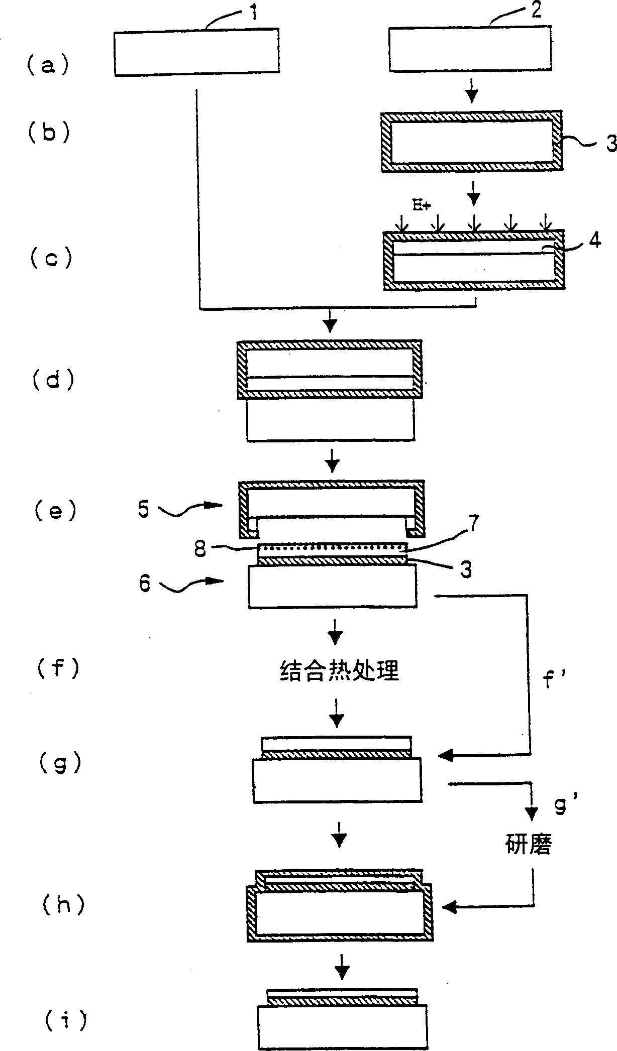
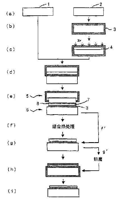
[0050] In the crystal orientation (100) produced by the CZ method, a silicon single crystal ingot whose conductivity type is p-type and a resistivity of 20G·cm is sliced, and the ingot is processed to produce a silicon mirror wafer with a diameter of 200mm . Divide these into bonded chips and base wafers, according to figure 1 In the steps shown in (a) to (i), an SOI wafer is manufactured by using the ion implantation lift-off method of the present invention.

[0051] First, follow the figure 1 In (a) to (e), the bonded wafer 2 is peeled off to obtain an SOI wafer 6 . At this time, the thickness of the buried oxide film 3 is 400 nm, and main conditions such as implantation of other ions are as follows.

[0052] 1) Ion implantation conditions: H + Ions, implantation energy 90keV,

[0053] Injection line volume 6.5×10 16 / cm 2

[0054] 2) Stripping heat treatment conditions: N 2 Under air environment, 500℃, 30 minutes,

[0055] As described above, altho...


PUM


Abstract

A method for producing a bonded wafer by the ion implantation delamination method includes at least a step of bonding a bond wafer having a micro bubble layer formed by gaseous ion implantation and a base wafer serving as a support substrate and a step of delaminating the bond wafer at the micro bubble layer as a border to form a thin film on the base wafer. After the delamination of the bond wafer, the bonded wafer is subjected to a heat treatment in an atmosphere of an inert gas, hydrogen or a mixed gas thereof, then the bonded wafer is subjected to thermal oxidation to form a thermal oxide film on the surface of the thin film, and then the thermal oxide film is removed to reduce thickness of the thin film.

Description

technical field [0001] The present invention relates to a method of manufacturing a bonded wafer using an ion implantation debonding method, and particularly relates to a method of manufacturing an SOI wafer by bonding a silicon wafer implanted with hydrogen ions or the like as a support substrate to another wafer and then debonding it. Background technique [0002] Recently, as a method for manufacturing SOI (silicon on insulator) wafers, a method of manufacturing SOI wafers by peeling off ion-implanted wafers after bonding (ion implantation stripping method: also called Smart Cut method (registered trademark) ) technology) began to attract attention again. This ion implantation stripping method is a technique as described below (refer to Japanese Patent Application Laid-Open No. 5-211128): an oxide film is formed on at least one of the two silicon wafers, and an oxide film is formed on the other silicon wafer (bonded wafer). After injecting gas ions such as hydrogen ions ...

Claims


Application Information

Patent Timeline
Patent Type & Authority Applications(China)
IPC IPC(8): H01L21/30H01L21/46H01L21/762H01L21/8238H01L27/12
CPCH01L21/76254Y10S438/977H01L21/20
Inventor 阿贺浩司富泽进一三谷清
Owner SHIN-ETSU HANDOTAI CO LTD
Learn More