Declining lug structure on surface of reflector and its mfg method

A manufacturing method and technology of reflecting mirror surface, which can be applied to photosensitive materials, nonlinear optics, instruments, etc. for opto-mechanical equipment, and can solve the problems of increasing manufacturing cost, time-consuming, complicated and time-consuming processes, etc.

Inactive Publication Date: 2003-05-07
JSR CORPORATIOON
View PDF0 Cites 8 Cited by
  • Summary
  • Abstract
  • Description
  • Claims
  • Application Information

AI Technical Summary

Problems solved by technology

[0006] However, the above process needs to constantly move the photomask to expose the photoresist in different regions separately, and also needs to adjust the position of the photomask and the exposure intensity or time, which has the disadvantages of time-consuming and increased manufacturing costs.
In addition, in order to form a single bump with an inclination angle, it is necessary to move the photomask of this single opening multiple times and expose it, and then it can be completed after development and heating. If the number of bumps is to be increased on the mirror surface, that is, increase The concave and convex degree on the mirror surface makes the light scattering better, the process will be more complicated and time-consuming, and it is very unsuitable for mass production

Method used


Image

  • Declining lug structure on surface of reflector and its mfg method
  • Declining lug structure on surface of reflector and its mfg method
  • Declining lug structure on surface of reflector and its mfg method

Examples


Embodiment 1

[0040] In this embodiment, a photomask with slits is used to form the inclined bump structure on the mirror surface of the present invention. Wherein, the photomask includes m groups of patterns, and each group of patterns is composed of n strips of different widths arranged with a gap from wide to narrow, and at least one is added between each gap. The narrow strips form multi-slits on the photomask. Wherein, m is a positive integer ≥1, and n is a positive integer ≥2.

[0041] refer to Figure 4 , which shows a partial top view of a photomask according to Embodiment 1 of the present invention. The photomask 400 includes m groups of patterns, and each group of patterns consists of n strips (401) 1 , (401) 2 , (401) 3 、...(401) n Composition, and its width is W respectively 1 , W 2 , W 3 ,...,W n . The gap between the strips is d in sequence 1 、d 2 、d 3 ,...,d n , and take a narrow strip in the gap as an example, the width of the narrow strip is s 1 , s 2 , s ...

Embodiment 2

[0051] In the second embodiment, another photomask pattern with slits is provided for the manufacturing of the present invention to obtain the inclined bump structure. After fabrication, the photoresist of Example 2 has a higher degree of bump aggregation than that of Example 1, that is, the degree of concavo-convexity on the reflective mirror surface is improved, and the light scattering effect is better.

[0052] The photomask of the second embodiment includes m groups of patterns (m is a positive integer ≥ 1), and each group of patterns consists of a plurality of strips arranged from wide to narrow, and the gaps between the strips Also take a narrow strip as an example. The m groups of patterns can be randomly arranged on the photomask, or they can be arranged neatly like a matrix, for example, m' groups of long sides and n' groups of wide sides (m=m'×n'). In this embodiment, for the convenience of description, m groups of figures are randomly arranged, and each set of fig...


PUM


Abstract

A method for processing tilting projection structure on a reflector face at least includes providing a substrate forming a photo element layer which is zoned to form multiple ladders with different bottom areas connected with each other; smoothing these ladders to form multiset projections with a tilt angle. This invention uses optical diffraction method and a special light mask to make the applied reflective liquid crystal display screen reach the aim of having both reflecting brightness and wide and angle of field by single exposure.

Description

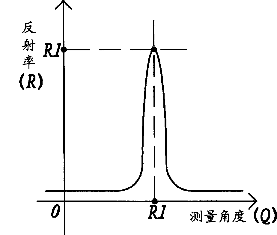
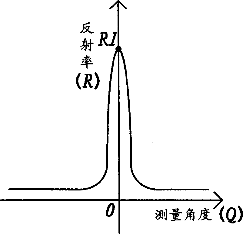
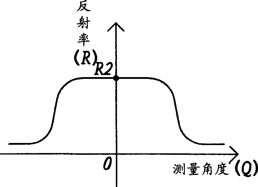
technical field [0001] The invention relates to an inclined bump structure on a reflective mirror surface and a manufacturing method thereof, in particular to an inclined bump structure formed on a reflective mirror surface of a reflective liquid crystal display screen by an optical diffraction method and a manufacturing method thereof. Background technique [0002] For reflective liquid crystal displays (reflective liquid crystal displays), in addition to paying attention to the brightness reflected by the liquid crystal display (LCD), attention must also be paid to whether the viewing angle is wide. Therefore, how to design a reflector that enables the liquid crystal display to have both reflective brightness and a wide viewing angle is an important research direction at present. [0003] refer to figure 1 , which is a graph showing the relationship between the light reflectivity of a traditional mirror surface and the measurement angle. Wherein,...

Claims


Application Information

Patent Timeline
IPC IPC(8): G02F1/1335G03F7/09
Inventor 简锦诚朱正仁
Owner JSR CORPORATIOON
Why Eureka
Try Eureka