


Quick Research
Generate reliable direction feasibility study reports for your R&D in just a few steps.

Technical Q&A
Discover and master advanced knowledge NOW. Basics, ideas, possibilities, all at once.

Find Solutions
As an expert in R&D theories, this can generate solutions to your technical problems instantly.

Evaluate Feasibility
Analyze your overall solution with one click, know your potential R&D risks in advance.

Monitor Landscape
Get weekly tech updates, stay abreast of the latest tech innovations and key insights.
Speed changeable motor for power tool
A technology of power tools and electric motors, applied in the field of portable power tools, can solve the problems of reducing the overall length of the drilling machine and having no space to meet the requirements
- Summary
- Abstract
- Description
- Claims
- Application Information
AI Technical Summary
Problems solved by technology
Method used
Image

Examples
Embodiment Construction
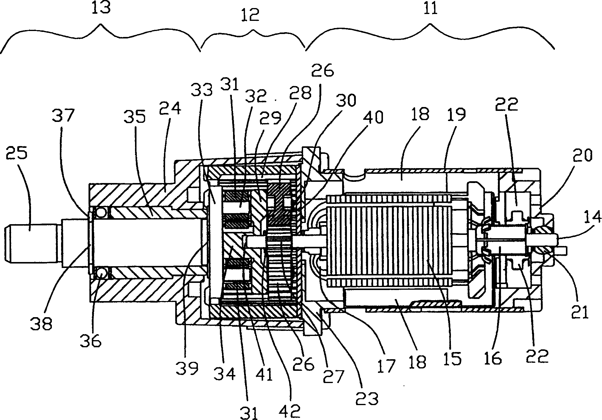
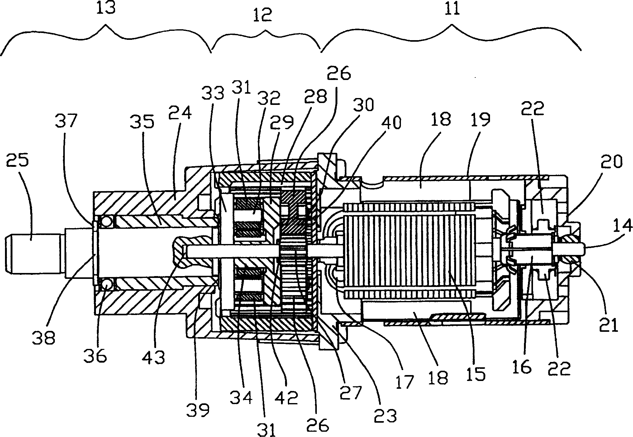
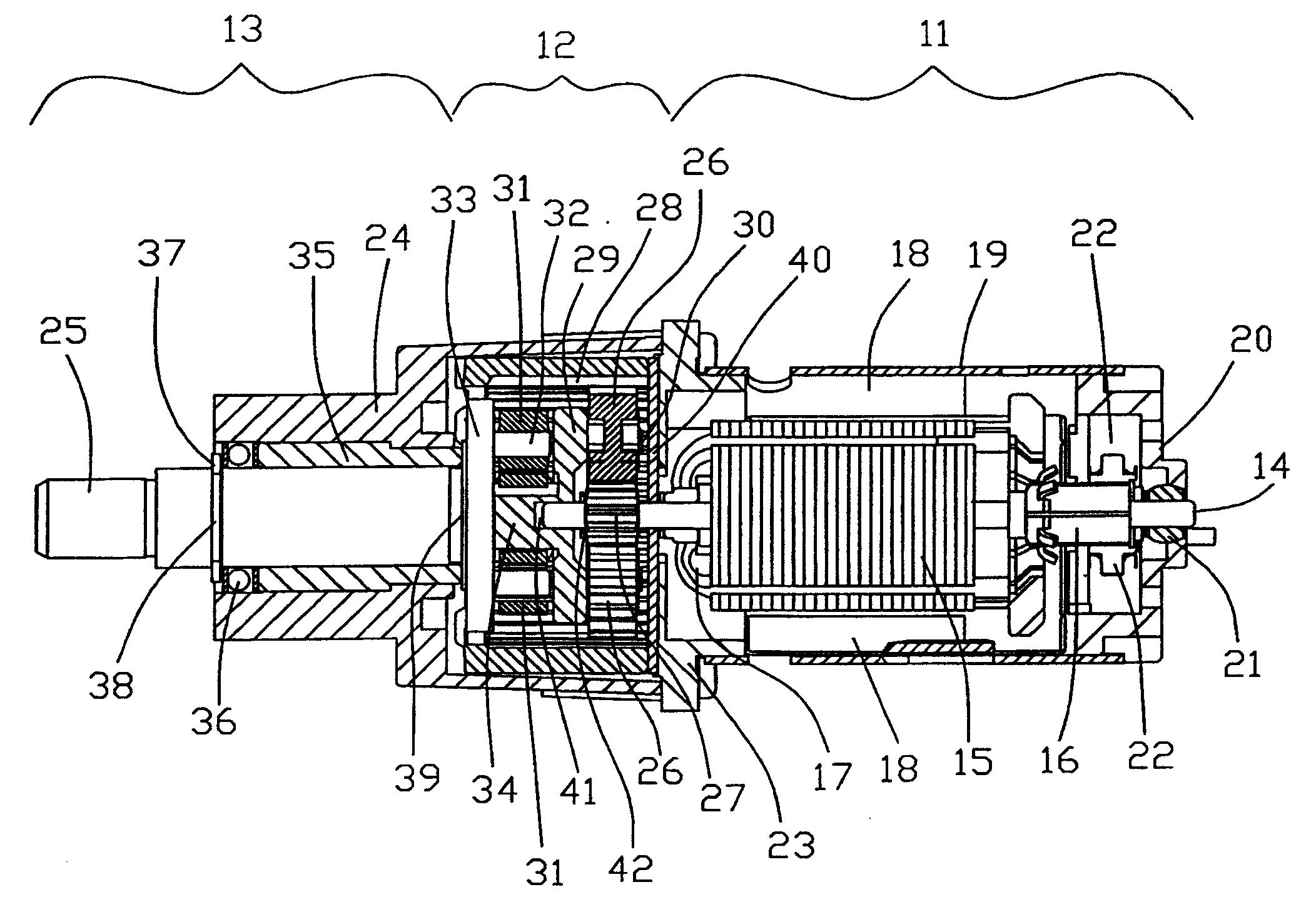
[0016] figure 1 Indicates a motor / gearbox combination for a portable power tool such as a drill or electric screwdriver. The combined device has a small overall length. The assembly is divided into two parts, namely: a motor part 11 and a gearbox part 12 comprising an output part 13 .
[0017] The motor section 11, shown on the right, contains a DC motor with a permanent magnet stator and a wound rotor. The rotor comprises a shaft 14 , a rotor core 15 and a rectifier 16 mounted on the shaft 14 , with rotor windings 17 wound around the rotor core 15 and ending in the rectifier 16 .
[0018] The stator 18 includes permanent magnets placed in a tubular casing 19 . A throttle end cap 20 closes off the right hand end of the tube 19 . The throttle cover 20 is made of an insulating synthetic resin and supports bearings 21, brush units 22 and terminals (not shown) of the motor. Bearing 21 is a self-aligning oil soaked sintered bronze bushing into which one end of the rotor shaft ...
PUM
 Abstract
Description
Claims
Application Information
 - R&D Engineer
- R&D Manager
- IP Professional
- Industry Leading Data Capabilities
- Powerful AI technology
- Patent DNA Extraction
Browse by: Latest US Patents, China's latest patents, Technical Efficacy Thesaurus, Application Domain, Technology Topic, Popular Technical Reports.
© 2024 PatSnap. All rights reserved.Legal|Privacy policy|Modern Slavery Act Transparency Statement|Sitemap|About US| Contact US: help@patsnap.com