Rolling bearing comprising three concentric rings

A technology of rolling bearings and rolling elements, applied in rolling contact bearings, roller bearings, bearings in rotating motion, etc., can solve problems such as increasing the bearing width

Pending Publication Date: 2020-10-30
AB SKF
View PDF2 Cites 0 Cited by
  • Summary
  • Abstract
  • Description
  • Claims
  • Application Information

AI Technical Summary

Problems solved by technology

This configuration significantly increases the width of the bearing

Method used


Image

  • Rolling bearing comprising three concentric rings
  • Rolling bearing comprising three concentric rings
  • Rolling bearing comprising three concentric rings

Examples


Embodiment Construction

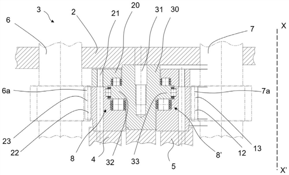
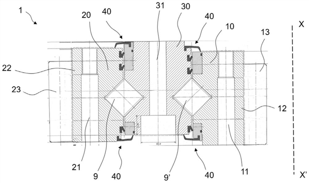
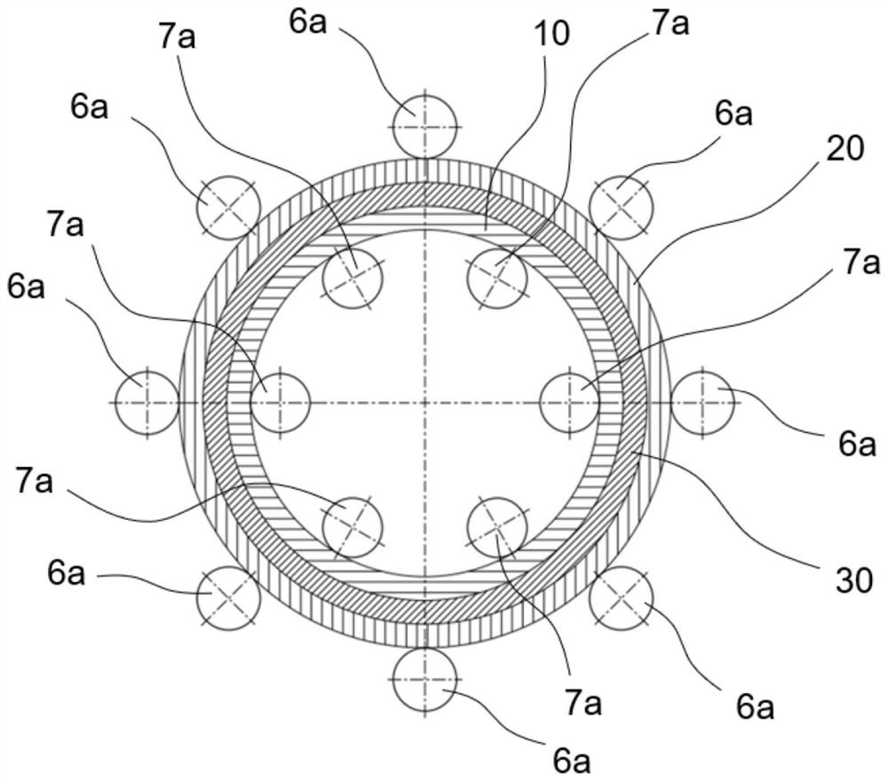
[0049] Figure 1 to Figure 3 A rolling bearing 1 comprising an inner ring 10 , an outer ring 20 and an intermediate ring 30 is shown. These three rings are arranged concentrically around the longitudinal axis XX'. The intermediate ring 30 is disposed between the inner ring and the outer ring in the radial direction.

[0050] At least one row of rolling elements is disposed between the outer ring and the middle ring, and at least one row of rolling elements is disposed between the inner ring and the middle ring.

[0051] The intermediate ring comprises a plurality of attachment means 31 for fixing the bearing to the frame 2 of the machine 3 .

[0052] The outer ring comprises a plurality of attachment means 21 for fixing the first machine element 4 to the bearing.

[0053] The outer ring comprises a radially outer peripheral portion 22 on which geartoothing 23 is arranged.

[0054] The inner ring comprises a plurality of attachment means 11 for fixing the second machine ele...


PUM


Abstract

A rolling bearing (1) includes an inner ring (10), an outer ring (20) and a middle ring (30), the rings (10, 20, 30) being concentrically arranged around a central axis (XX') so that the middle ring is arranged radially between the inner ring and the outer ring; at least one row of rolling elements interposed between the inner ring and the middle ring; at least one row of rolling elements interposed between the middle ring and the outer ring. The inner ring (10) has a radially inner circumferential portion (12) with a gear toothing (13) and the outer ring (20) has a radially outer circumferential portion (22) with a gear toothing (23).

Description

technical field [0001] The invention relates to the field of rolling bearings comprising three concentric rings, in particular of large diameter rolling bearings used in tunnel boring machines. Background technique [0002] Large diameter rolling bearings generally comprise two concentric inner and outer rings, and at least one row of rolling elements radially interposed between the rings. It is known to provide gear teeth on one of the inner and outer rings for driving said ring in rotation by means of suitable drive means. Such a bearing is known from US-2017-0356491-A1. [0003] Rolling bearings with three concentric rings are also known. For example, in DE-102004035587-A1 at least one of the rings is provided with an axial extension on which a bevel gear is arranged. This arrangement significantly increases the width of the bearing. [0004] There seems to be room for improvement. Contents of the invention [0005] According to a first aspect of the present invent...

Claims


Application Information

Patent Timeline
IPC IPC(8): F16C19/54F16C19/56F16C33/58F16C33/78E21D9/11
CPCF16C19/545F16C19/56F16C33/581F16C33/7809E21D9/11F16C2352/00F16C2300/14F16C2361/61F16C19/38F16C33/805F16C19/26F16C33/58F16C2360/31F16C19/55
Inventor 布鲁诺·卡波尔迪
Owner AB SKF
Why Eureka
Try Eureka