High-power microwave polarization conversion super-lens antenna

A high-power microwave and polarization conversion technology, applied in the field of radiating antennas, can solve the problems that the horn antenna does not have the polarization conversion function and the axial direction is not compact enough.

Active Publication Date: 2020-08-25
NAT UNIV OF DEFENSE TECH
View PDF4 Cites 0 Cited by
  • Summary
  • Abstract
  • Description
  • Claims
  • Application Information

AI Technical Summary

Problems solved by technology

[0005] The technical problem to be solved by the present invention is to provide a new type of high-power microwave polarization conversion metalens antenna, which has a compact structure and high gain, and is used to solve the problem that the existing horn antenna does not have the polarization conversion function, and it is not compatible with the circular pole of the waveguide. When the carburetor is matched, the axial direction is not compact enough, etc.

Method used


Image

  • High-power microwave polarization conversion super-lens antenna
  • High-power microwave polarization conversion super-lens antenna
  • High-power microwave polarization conversion super-lens antenna

Examples


Embodiment 1

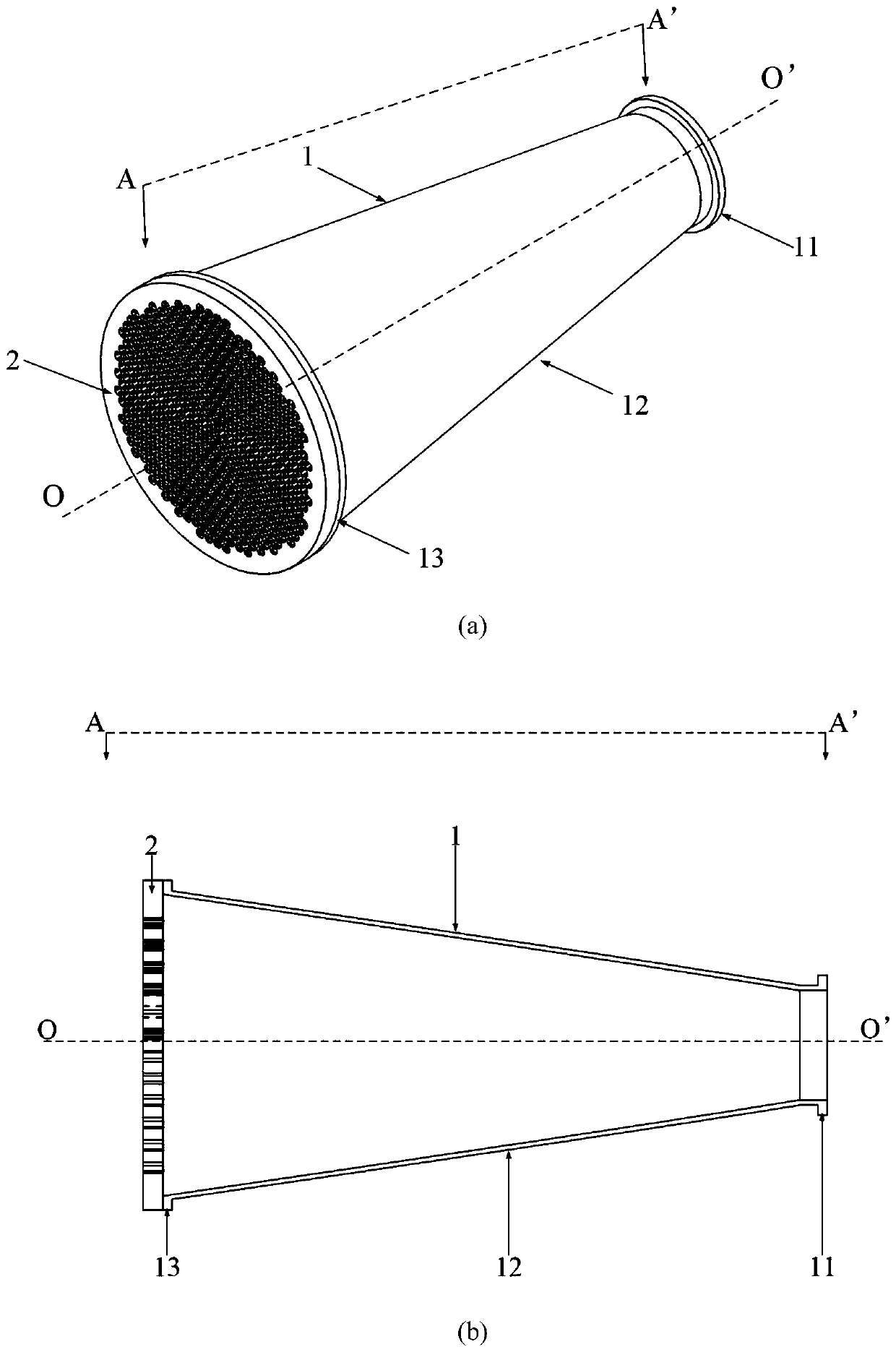
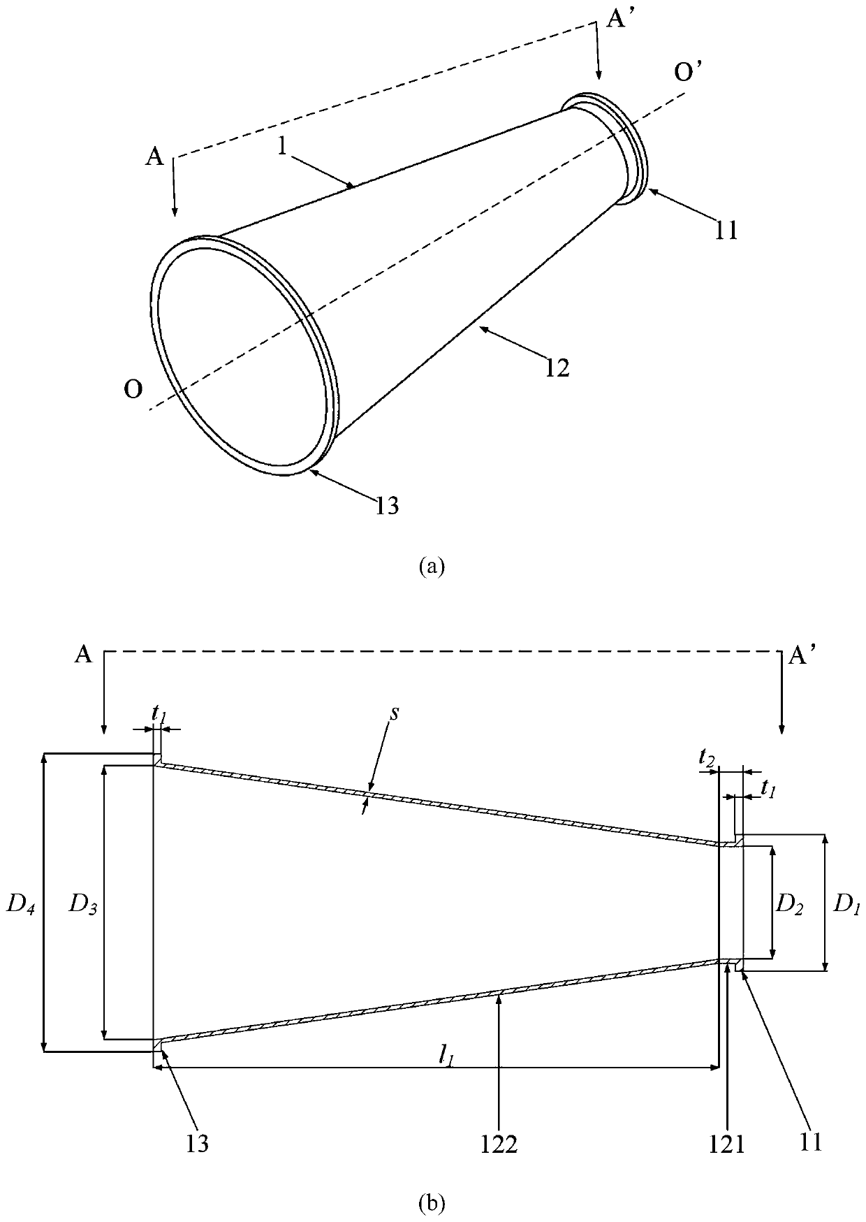
[0037] The embodiment of the high-power microwave mode conversion horn antenna of the designed center frequency f=14.25GHz (that is, the frequency of the input microwave source is 14.25GHz, and the corresponding microwave wavelength is 21.05mm) is:

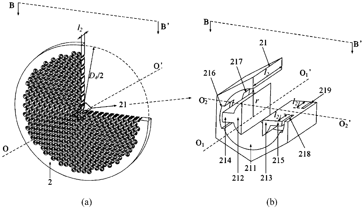
[0038] The horn antenna 1 adopts a conical horn antenna, wherein the inner diameter D of the circular waveguide 121 and the conical waveguide 122 in the conical horn 12 is close to the microwave source end 2 =140mm, circular waveguide 121 length t 2 =30mm, the inner diameter D of the conical waveguide 122 away from the microwave source end 3 =340mm, axial length l 1 =703mm; the outer diameter of the first flange 11 D 1 =170mm, the outer diameter of the second flange 13 D 4 =370mm, the thicknesses of the first flange 11 and the second flange 13 are both t 1 =10mm, waveguide wall thickness s=5mm; the diameter of the polarization conversion metalens 2 is equal to the outer diameter of the second flange 13, both are D 4 = 370mm. ...


PUM


Abstract

The invention discloses a high-power microwave polarization conversion super-lens antenna, and aims to solve the problems that an existing horn antenna does not have a polarization conversion functionand is not compact enough in the axial direction when matching a waveguide circular polarizer. The antenna is composed of a horn antenna and a polarization conversion super lens. The horn antenna iscomposed of a first flange plate, a conical horn and a second flange plate. The polarization conversion super-lens is formed by arranging and combining a plurality of polarization conversion super-lens units in a honeycomb shape, a through hole is drilled in the center of each polarization conversion super-lens unit, two arch-shaped columns are arranged in each through hole and connected with theinner wall of the through hole through supporting rods respectively, and two matching grooves are formed in the two ends of each polarization conversion super-lens unit respectively. The cross sectionof each polarization conversion super-lens unit is a regular hexagon, and the polarization conversion super-lens units are closely arranged into a circle. According to the invention, the thickness isabout one free space wavelength, the axial direction is more compact, the power capacity is higher, a linear polarization mode can be directly converted into a circular polarization mode, and the circular polarization microwave mode is radiated into the free space.

Description

technical field [0001] The invention relates to a radiation antenna in the technical field of high-power microwaves, in particular to a high-power microwave polarization conversion metalens antenna capable of realizing circularly polarized radiation. Background technique [0002] As an emerging subject, high power microwave has broad application prospects in both military and civilian fields. As an important part of the high-power microwave system, the high-power radiation antenna determines whether the energy generated by the high-power microwave source can be effectively radiated or concentrated on the target. At present, most high-power microwave radiation antennas are linearly polarized antennas, which are difficult to play a role in circularly polarized receiving electronic equipment, and part of the energy will be lost due to polarization mismatch. Therefore, in order to improve the effect of high-power microwave antennas and expand the application range of high-power...

Claims


Application Information

Patent Timeline
Patent Type & Authority Applications(China)
IPC IPC(8): H01Q13/02H01Q1/50H01Q15/04H01Q15/24
CPCH01Q13/02H01Q1/50H01Q15/04H01Q15/244
Inventor 袁成卫赵旭浩张建德张强孙云飞
Owner NAT UNIV OF DEFENSE TECH
Why Eureka
Try Eureka