Electric lamp

A technology for discharge lamps and lamp tubes, which is applied to the parts of gas discharge lamps, etc., and can solve the problems of ceramic sealing mixtures being difficult to grasp and connecting to lamp tube shells, etc.

Inactive Publication Date: 2007-01-31
KONINKLIJKE PHILIPS ELECTRONICS NV
View PDF2 Cites 0 Cited by
  • Summary
  • Abstract
  • Description
  • Claims
  • Application Information

AI Technical Summary

Problems solved by technology

It has proven difficult to control the amount of ceramic sealing compound that should be provided if it is to substantially surround the second conductor without being able to directly connect the first part to the lamp envelope

Method used


Image

  • Electric lamp
  • Electric lamp
  • Electric lamp

Examples


Embodiment Construction

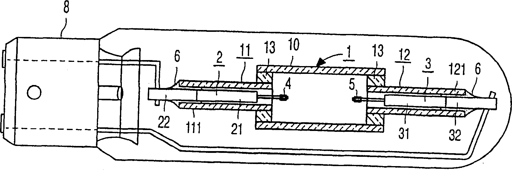
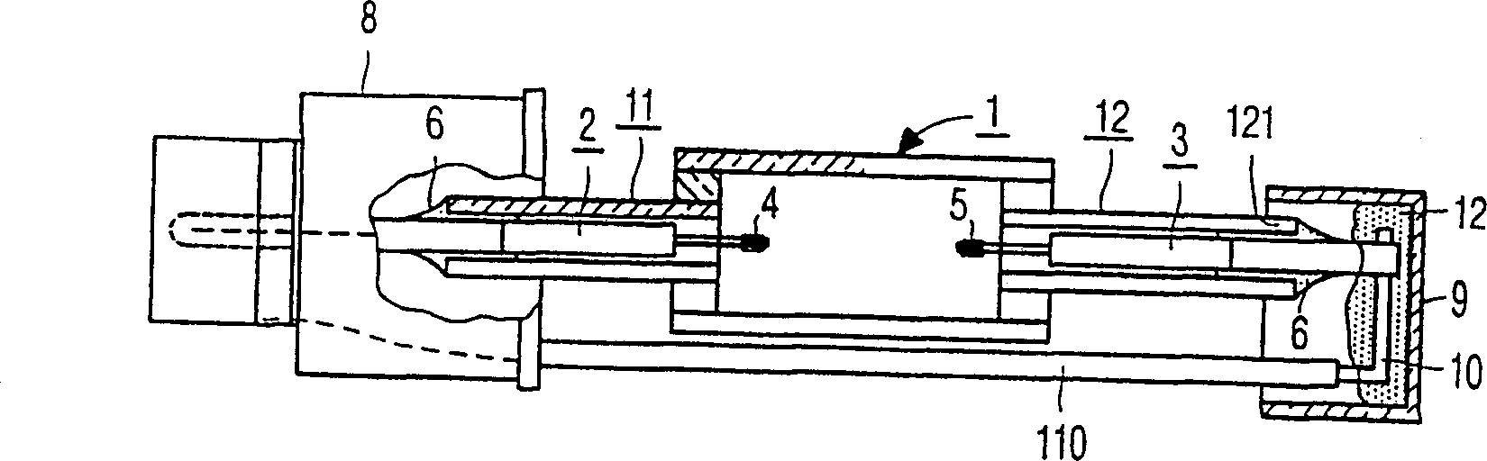
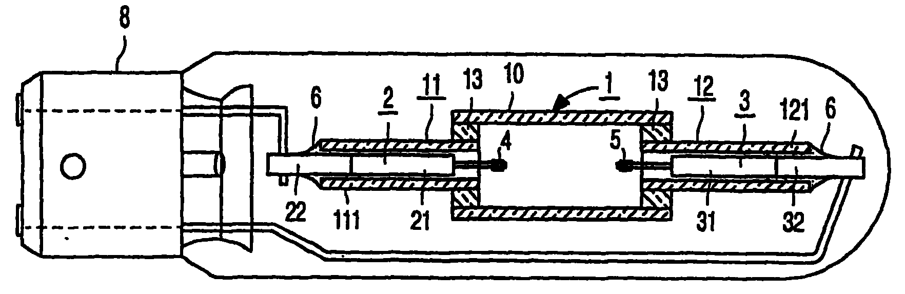
[0030] exist figure 1 , the discharge lamp has a tubular light-transmitting ceramic lamp vessel 1, in the figure made of polycrystalline aluminum oxide material, and a first and a second current conductor 2, 3, which are embedded in the lamp vessel 1, facing each other, each supports an electrode 4, 5 in the lamp vessel 1, namely the tungsten electrodes welded to the current conductors 2 and 3 shown in the figure. The ceramic sealing mixture 6 in the figure is 30% by weight of aluminum oxide, 40% by weight of silicon oxide and 30% by weight of dysprosium oxide, which seals the circumference of said conductors 2, 3 to the lamp in a gas-tight manner during the melting process. On the shell 1. The ionizable fill material within the lamp envelope consists of argon, an inert gas, and metal halides. A mixture of iodides of sodium, thallium and dysprosium is used as the metal halide. At least the first current conductor 2 has a first halogenation-resistant part 21 in the lamp vess...


PUM


Abstract

The electric lamp has a ceramic lamp vessel (1) having a filling of rare gas and metal halide. Current conductors (2, 3) which support electrodes (4, 5) inside the discharge vessel (1) enter the discharge vessel (1) in a gastight manner through a ceramic sealing compound (6). At least one of the current conductors (2, 3) has inside the lamp vessel (1) a first, halogen-resistant part (21, 31) which is selected from tungsten silicide, molybdenum aluminide, molybdenum boride, pentamolybdenum trisilicide and combinations of at least two of these intermetallic compounds. These compounds have a coefficient of thermal expansion which corresponds to that of the discharge vessel (1). It is thereby prevented that the discharge vessel starts leaking if the ceramic sealing compound (6) extends beyond the first part (21, 31). As a result of their coefficient of thermal expansion, the intermetallic compounds may constitute the second part (22, 32) of the current conductors (2, 3) as well, which part (22, 32) is surrounded by the ceramic sealing compound (6) in a gastight manner.

Description

technical field [0001] The invention relates to a discharge lamp comprising: [0002] A light-transmitting ceramic lamp shell; [0003] a first and a second current conductor embedded in said lamp envelope, each supporting an electrode within the lamp envelope; [0004] a ceramic sealing compound which hermetically seals the circumference of the current conductor to the lamp envelope in a gas-tight manner; [0005] an ionizable fill within the envelope of a lamp comprising an inert gas and a metal halide, [0006] At least said first current conductor has a first halogenation resistant portion within said lamp envelope, and a second portion extending from said ceramic sealing compound to the exterior of said lamp envelope. Background technique [0007] Such a discharge lamp is described in European Patent Document EP-A-0 587 238 . [0008] The current conductors of such discharge lamps must have a linear coefficient of thermal expansion which varies with the coefficient ...

Claims


Application Information

Patent Timeline
IPC IPC(8): H01J61/36
CPCH01J61/36
Inventor E·范德沃尔特H·J·德罗伊宁F·H·范利罗普P·A·赛宁M·F·C·维莱姆森M·波莱克
Owner KONINKLIJKE PHILIPS ELECTRONICS NV
Why Eureka
Try Eureka