
Optical diffusion barrier and relative back light module

A technology of light diffusing film and light diffusing layer, applied in optics, nonlinear optics, heating methods, etc., can solve the problems of insufficient heat resistance, poor strength, thermal deformation, etc.

Inactive Publication Date: 2007-01-10
KEIWA INCORPORATED
View PDF4 Cites 1 Cited by
  • Summary
  • Abstract
  • Description
  • Claims
  • Application Information

AI Technical Summary

Problems solved by technology

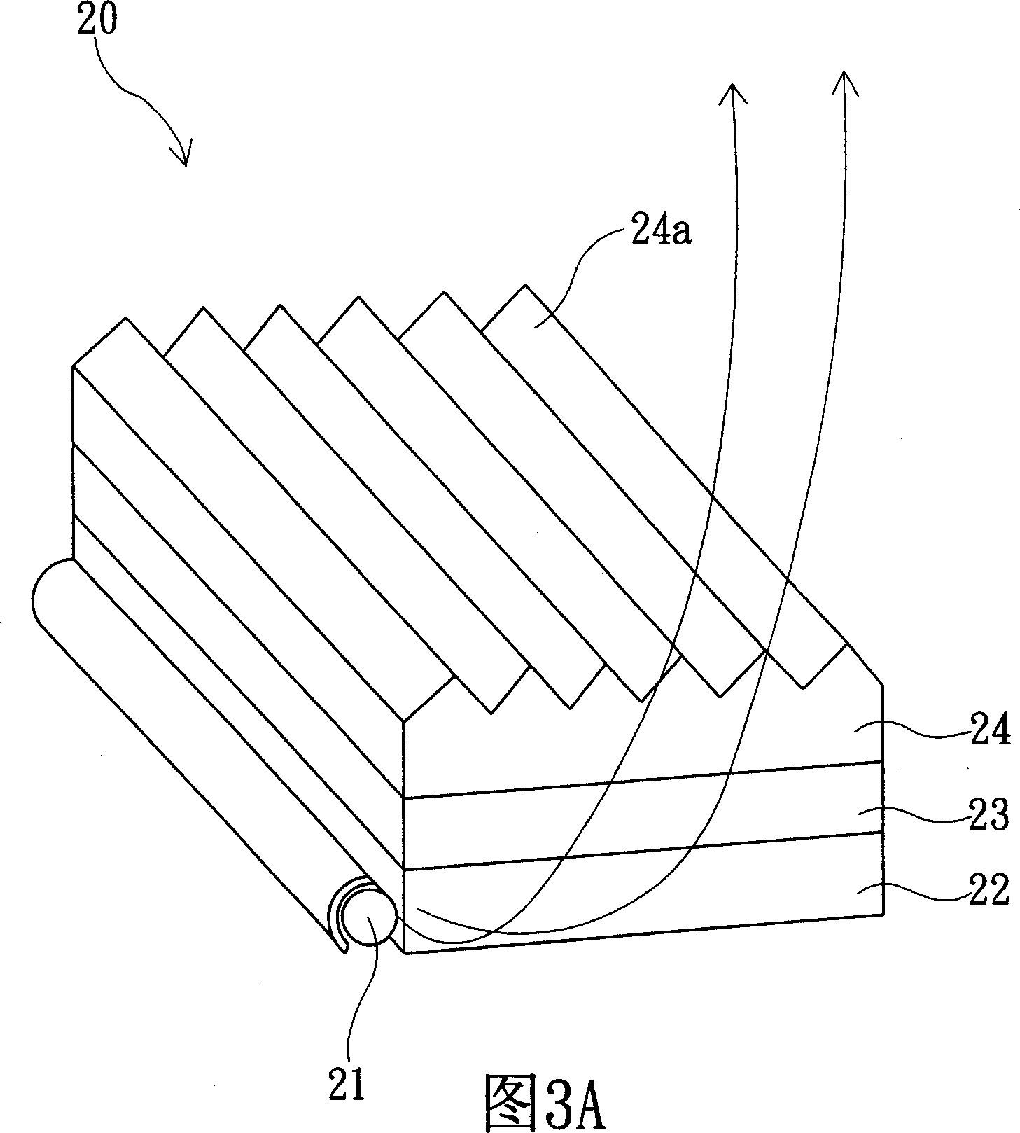
Therefore, the light-diffusing film 23 will cause thermal deformation, and the part will be bent, thus causing the defect of uneven picture.
[0007] Therefore, a technology for improving heat resistance has been developed (JP-A-2000-89007). In the binder 29 of the light-diffusing layer 27 of the light-diffusing film 23, the minute inorganic filler is dispersed and contained to achieve it; however This technology still has the following disadvantages: (a) the dispersibility of the tiny inorganic filler is poor, and heat resistance cannot be obtained sufficiently; (b) the adhesion between the tiny inorganic filler and the binder 29 is insufficient, and gaps will be generated at the interface between the two. Resulting in poorer intensity and reduced penetration of light

Method used


Image

  • Optical diffusion barrier and relative back light module
  • Optical diffusion barrier and relative back light module
  • Optical diffusion barrier and relative back light module

Examples


Embodiment 1

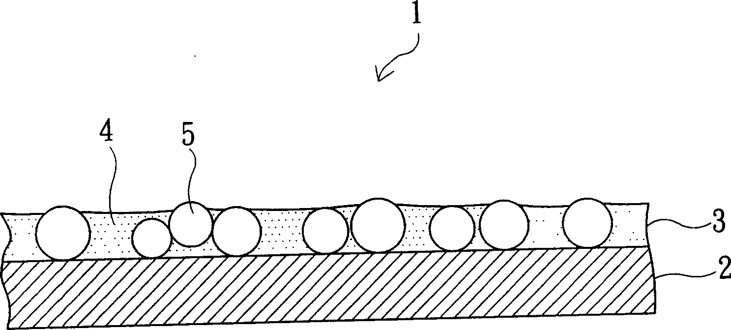
[0070] A coating liquid was prepared by mixing 50 units of acrylic resin beads ("MBX-15" from Sekisui Chemical Industry Co., Ltd.) with an average particle diameter of 15 μm in the polymer composition, and then the coating liquid was applied by the rolling method. On the surface of a 100 μm thick transparent polyester base material layer (“A-4300” manufactured by Toyobo Co., Ltd.), the coating thickness is 15 g / m 2 (solid content conversion), after making it harden, the light-diffusion film of Example 1 was obtained. The polymer composition includes: 100 units of adhesive resin composition, which also uses polyester polyol as a base polymer, and the polyester polyol has a cycloalkyl group; colloidal silica (voltaic silica) 50 units of "PL-1" manufactured by Sang Chemical Industry Co., Ltd., whose average particle diameter is 20 nm; and 5 units of hardener ("Coronet HX" manufactured by Japan Polyurethane Co., Ltd.).

Embodiment 2

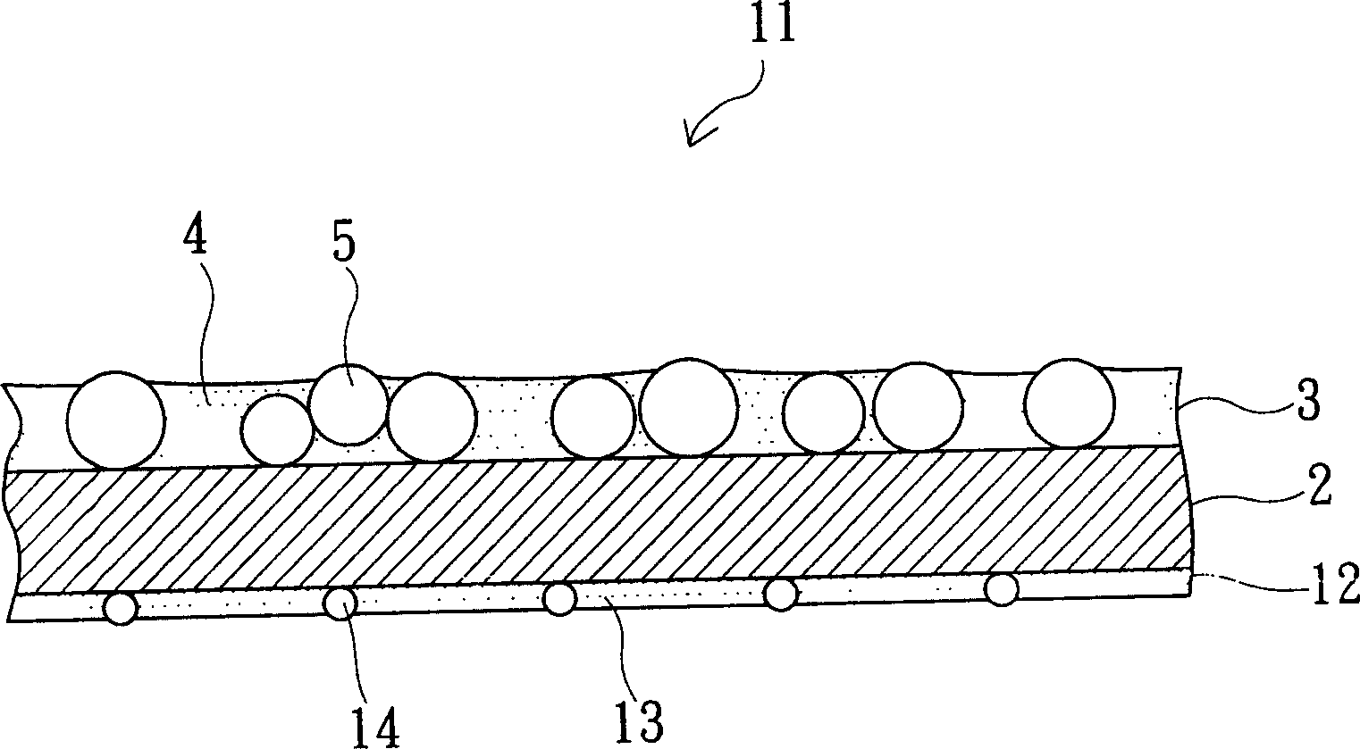
[0072] 10 units of acrylic resin beads ("MBX-5" from Sekisui Chemical Industry Co., Ltd.) having an average particle diameter of 5 μm were mixed with the above-mentioned polymer composition to prepare a coating liquid. Next, the coating liquid was applied by rolling coating method. Apply to the back of the above-mentioned base material layer, and its application thickness is 3g / m 2 (in terms of solid content), and hardened, the light-diffusion film of Example 2 was obtained in the same manner as in Example 1, except that the adhesion prevention layer was laminated.

Embodiment 3

[0074] The light-diffusion film of Example 3 was obtained like Example 1 except having used the adhesive resin composition ("RUB Medium SA" manufactured by Dainichi Seika Co., Ltd.). The adhesive resin composition uses acrylic polyol as the base polymer.


PUM

PropertyMeasurementUnit
The average particle sizeaaaaaaaaaa

Abstract

The present invention provided a light diffusion sheet which is capable of enhancing heat resistance, thermal dimensional stability and weather resistance while retaining transparency and which is less liable to sag, yellowing or the like even under heat generated by a lamp or ultraviolet ray irradiation, and provided a backlight unit which reduces luminance nonuniformity by using the light diffusion sheet. A light diffusion sheet is provided with a transparent base layer and a light diffusion layer stacked on the front surface of the base layer. The light diffusion layer contains a light diffusion agent in its binder. The binder is formed of a polymeric composition containing polyester polyol or acrylic polyol and a minute inorganic filler, wherein the average particle size of the minute inorganic filler is 5 nm to 50 nm.

Description

technical field [0001] The present invention relates to a light diffusion film and a related backlight module; and the light diffusion film has the function of diffusing transmitted light, and is especially suitable for a backlight module of a liquid crystal display device; and the backlight module uses the light diffusion film. Background technique [0002] Currently, liquid crystal display devices are commonly used in the backlight type in which the liquid crystal layer is irradiated from the back of the liquid crystal to make it emit light; and backlight devices such as edge light type and vertical type are installed on the bottom side of the liquid crystal layer. Basically, as shown in Figure 3 (a), it is a general edge-light type backlight module 20, which has: a lamp tube 21, which is linear, and serves as a light source; a light guide plate 22, which is a square plate, and its end The light-diffusing film 23 is arranged on the front side of the light guide plate 22 ; ...

Claims


Application Information

Patent Timeline
IPC IPC(8): G02B5/02G02F1/13357F24F7/00G02F1/1335H04R1/02H04R9/02H04R9/04
Inventor 上北正和峰尾裕
Owner KEIWA INCORPORATED
Learn More