
Controller for PWM/PAM motor

A technology of control device and motor, applied in the direction of control of electromechanical transmission device, motor generator control, AC motor control, etc. Effect

Inactive Publication Date: 2006-09-20
HITACHI LTD
View PDF0 Cites 1 Cited by
  • Summary
  • Abstract
  • Description
  • Claims
  • Application Information

AI Technical Summary

Problems solved by technology

However, insufficient consideration has been given to the working efficiency of the motor under PWM control

Method used


Image

  • Controller for PWM/PAM motor
  • Controller for PWM/PAM motor
  • Controller for PWM/PAM motor

Examples


Embodiment Construction

[0053] use below Figure 1 to Figure 7 The first embodiment of the present invention is explained.

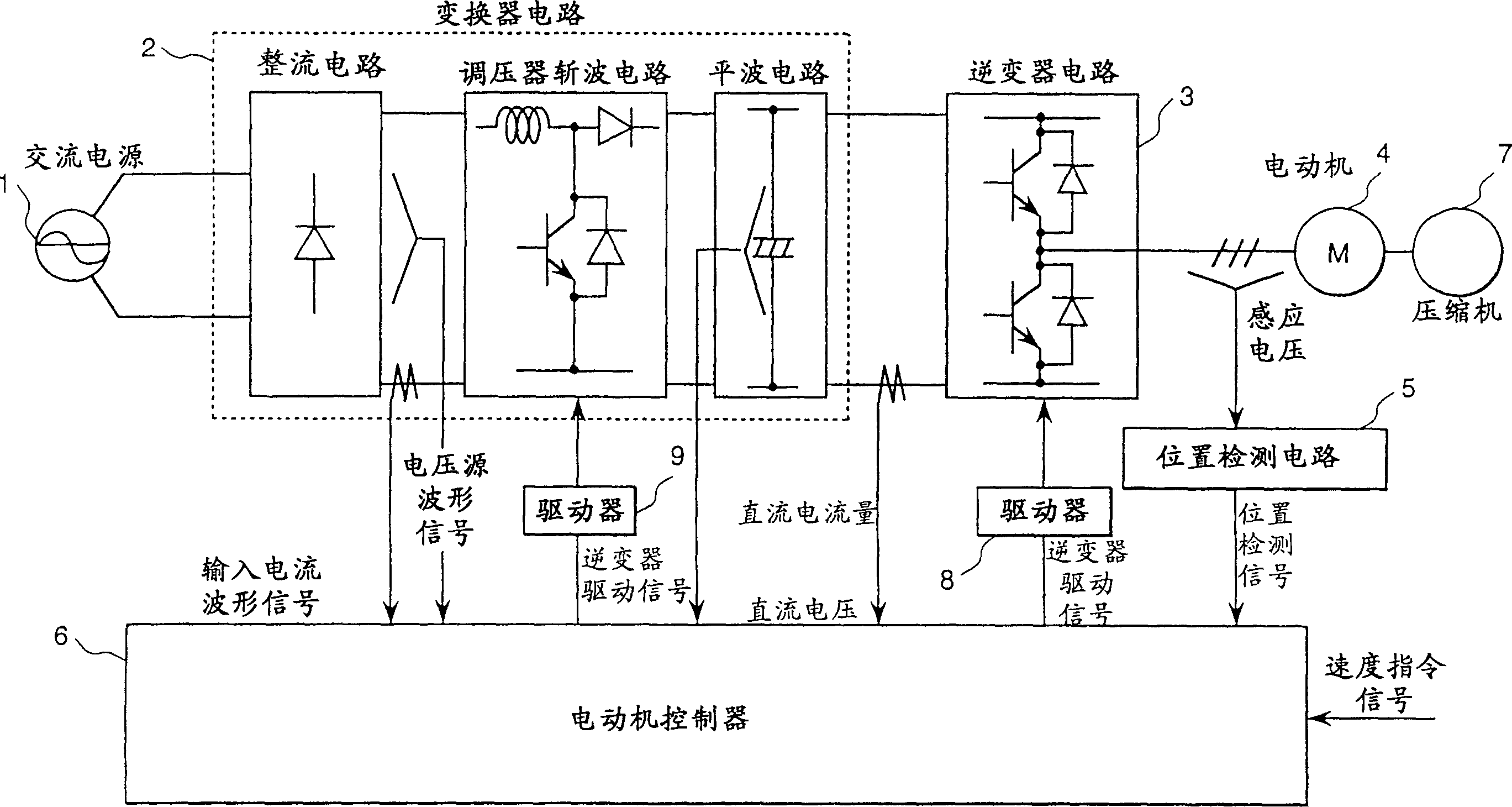
[0054] figure 1 It is an overall diagram of the present invention applied to the driving unit of the air conditioner compressor. This driving unit comprises a converter circuit 2, and it uses the rectifier circuit and voltage regulator chopper circuit to convert the AC voltage of the AC power source 1 into a DC power source and controls the DC voltage; an inverter circuit 3, which converts the DC voltage into The required AC voltage source is a motor controller, which controls the speed of the brushless DC motor 4 according to the speed command; a position detection circuit 5, which detects the magnetic pole position of the brushless DC motor 4; a driver 9, which controls the brushless DC motor according to the motor. The inverter driving signal of the inverter 6 drives the inverter circuit 2; a driver 8 drives the inverter circuit 3 according to the inverter driving signal ...


PUM


Abstract

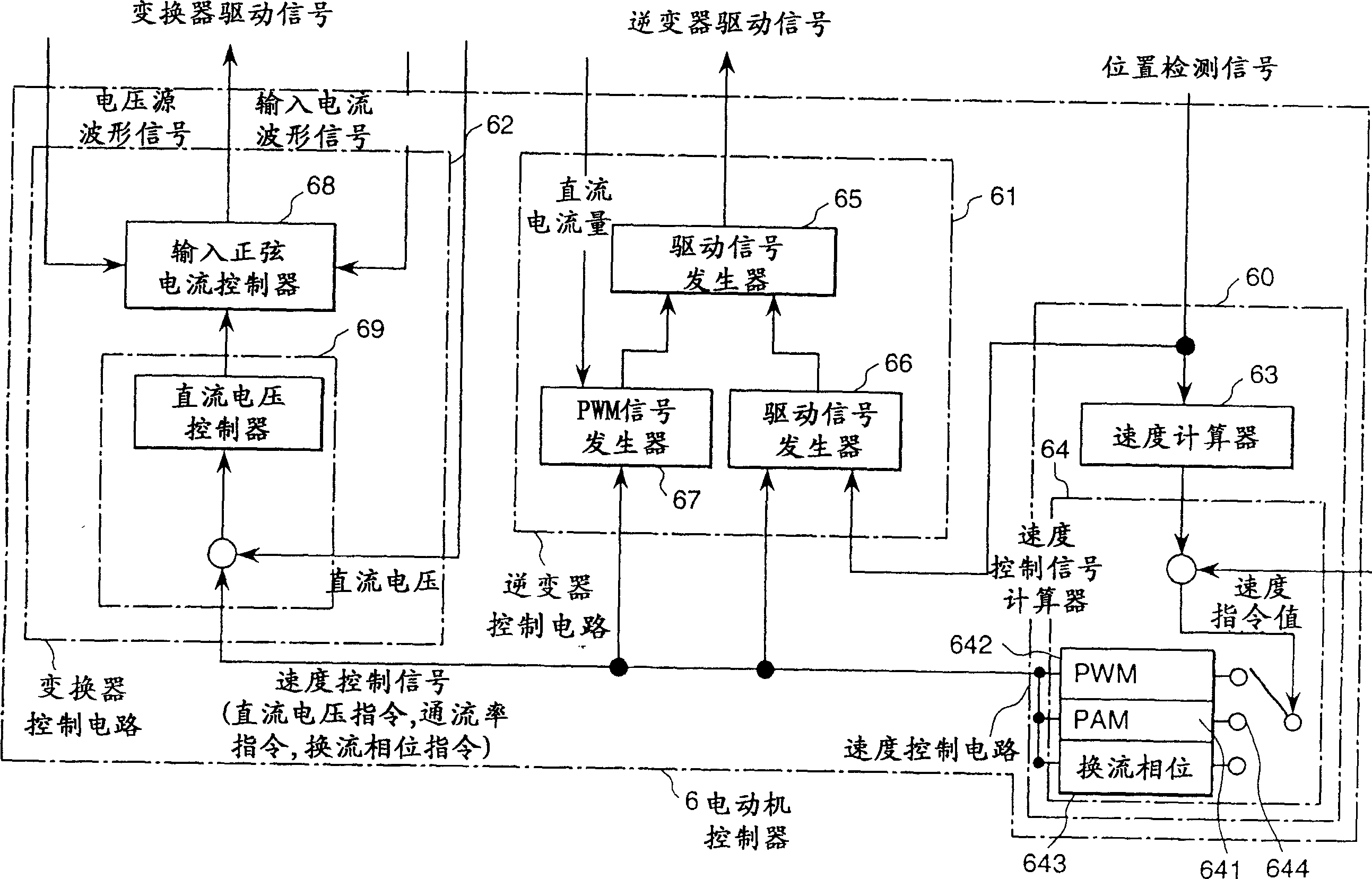
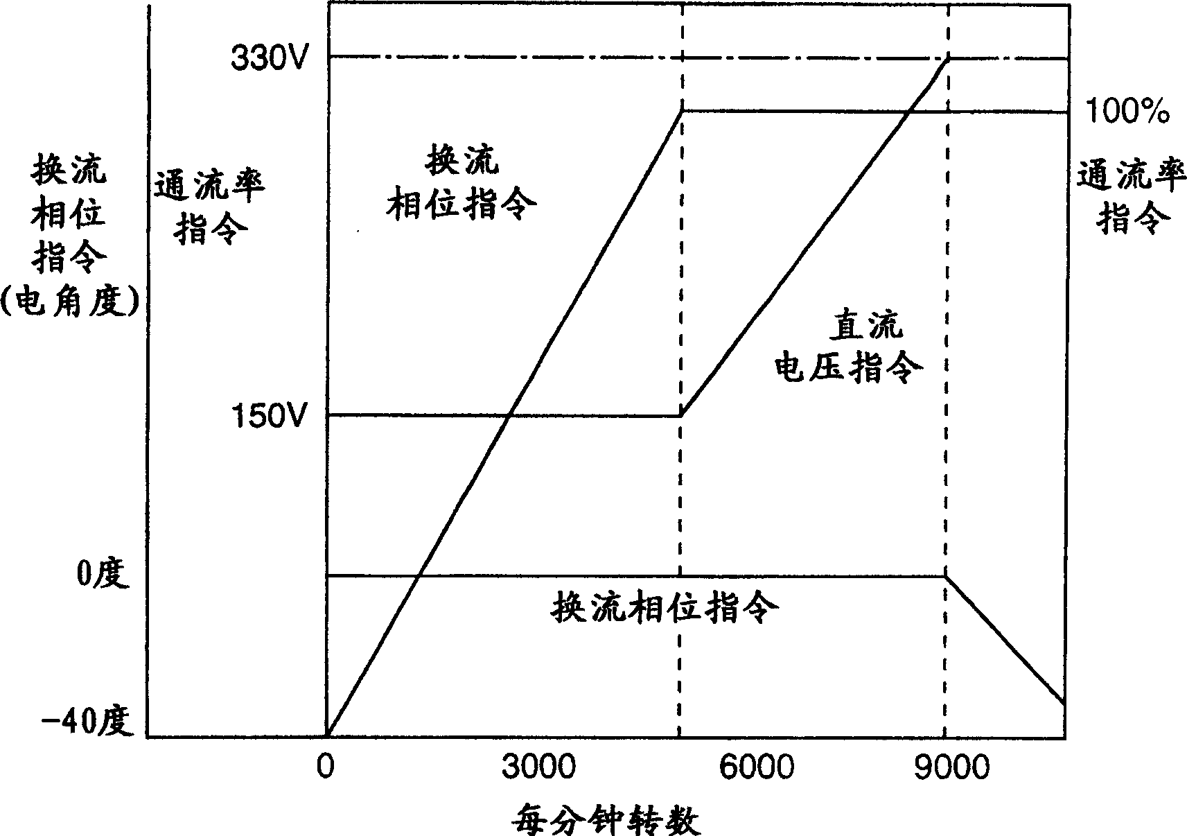
It has been a subject to be able to control a motor driving unit which is controlled by switching to / from PWM control from / to PAM control so that the maximum limit of the revolution per minute can be increased and, at the same time, the unit can be operated at the maximum efficiency in a steady-state operation. The above problem can be solved by a control means for a motor which comprises a converter circuit, an inverter circuit connected to the output of the converter circuit, amotor connected to the inverter circuit, and a speed control signal computing means that outputs a DC voltage command and a conduction ratio command to the converter control circuit and the inverter control circuit; wherein the speed of the motor is controlled by maintaining the DC voltage command to the converter control circuit constant but altering the conduction ratio command value to the inverter control circuit when the load to the motor is low, and by maintaining the conduction ratio command to the inverter control circuit constant but altering the DC voltage command to the converter control circuit; and said control means comprises a commutating phase control means that alters the commutating timing of the coil of the motor, and the motor is so controlled that the efficiency becomes the maximum limit in a steady-state operation and the revolution per minute becomes the maximum limit in a high-speed operation.

Description

technical field [0001] The present invention relates to a motor control device, and a control method of the motor, which can control the speed of the motor to reach the required revolutions per minute (r.p.m), and simultaneously control the input sinusoidal current to improve power factor and suppress Distortion of harmonic currents, and also relates to an air conditioner or refrigerator using the motor control device to drive a compressor drive motor and regulate room air. Background technique [0002] The control method described in Japanese Patent Application Laid-Open Publication No. SHO 63-224698 (1988) is a common method of a motor control device located in a rectifier circuit that rectifies alternating current and converts it into direct current power, which The speed of the motor is controlled by a combination of a power supply circuit that controls the DC voltage and a motor drive circuit. This method controls the motor speed by PWM (Pulse Width Modulation) control...

Claims


Application Information

Patent Timeline
Patent Type & Authority Patents(China)
IPC IPC(8): H02P27/06H02P6/08H02M7/48H02M5/458H02P21/02H02P21/04H02P21/18H02P21/24H02P23/02H02P23/03H02P23/16H02P27/08
CPCH02M5/4585H02P27/08H02P6/085
Inventor 能登原保夫川端幸雄田原和雄石井诚高仓雄八篠崎弘
Owner HITACHI LTD
Learn More