Insert valve for sectional radiator

A radiator and segmented technology, applied in the field of insertion valve, can solve the problems of high production cost and complex structure of the casing, and achieve the effect of low cost

Inactive Publication Date: 2006-03-22
DANFOSS AS
View PDF1 Cites 0 Cited by
  • Summary
  • Abstract
  • Description
  • Claims
  • Application Information

AI Technical Summary

Problems solved by technology

Therefore, the casing has a very complex structure and is expensive to produce

Method used


Image

  • Insert valve for sectional radiator
  • Insert valve for sectional radiator
  • Insert valve for sectional radiator

Examples


Embodiment Construction

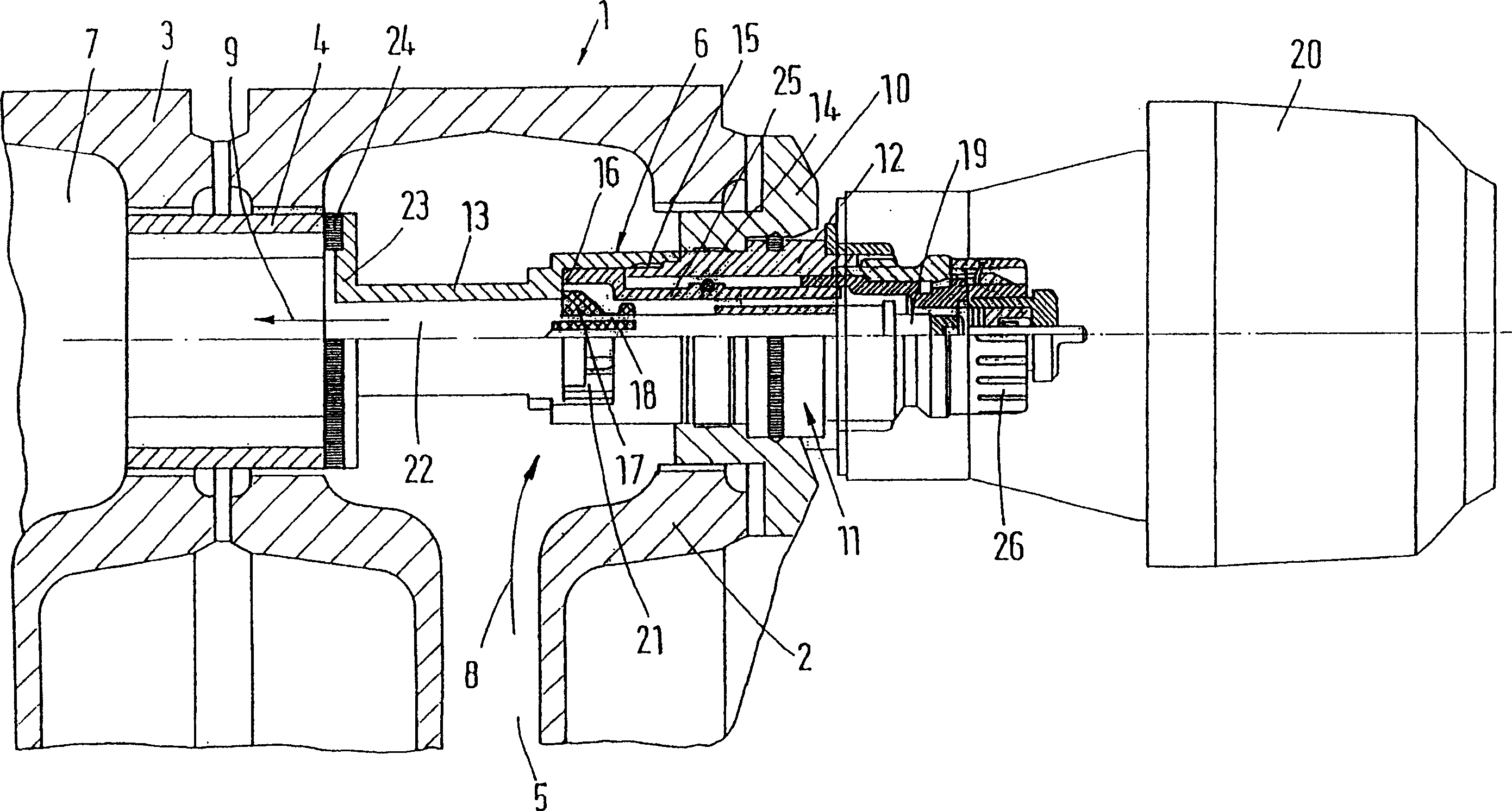
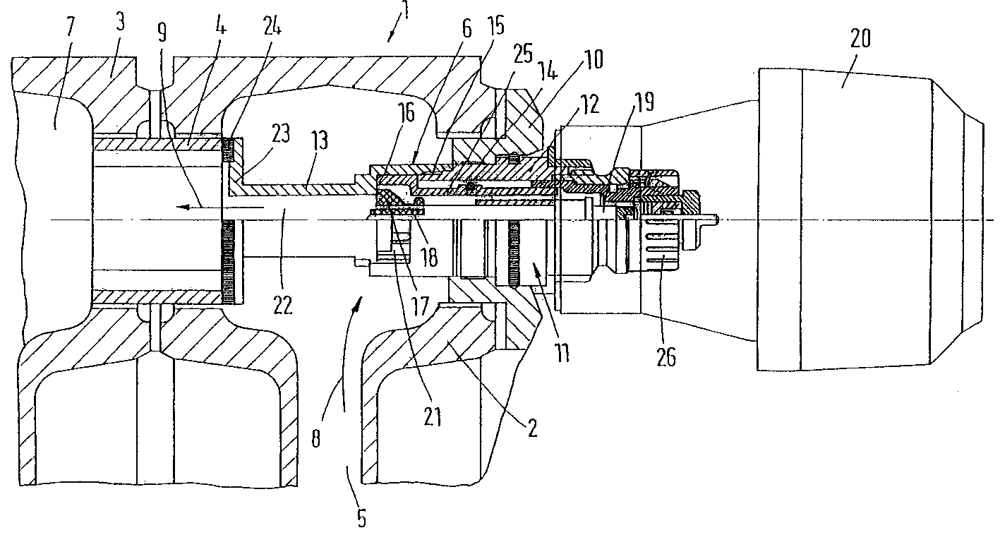
[0021] The segmented radiator 1 has a number of segments 2 , 3 which are connected by means of a partly right-hand threaded and partly left-hand threaded bushing 4 . The cavity 5 of the first section 2 is equipped with a positive flow connection at the bottom end. An insertion valve 6 controls the flow of the heating medium from the cavity 5 to the cavity 7 of the second section 3, which is connected to the return connection via a plurality of other sections. Arrows 8, 9 indicate the flow process.

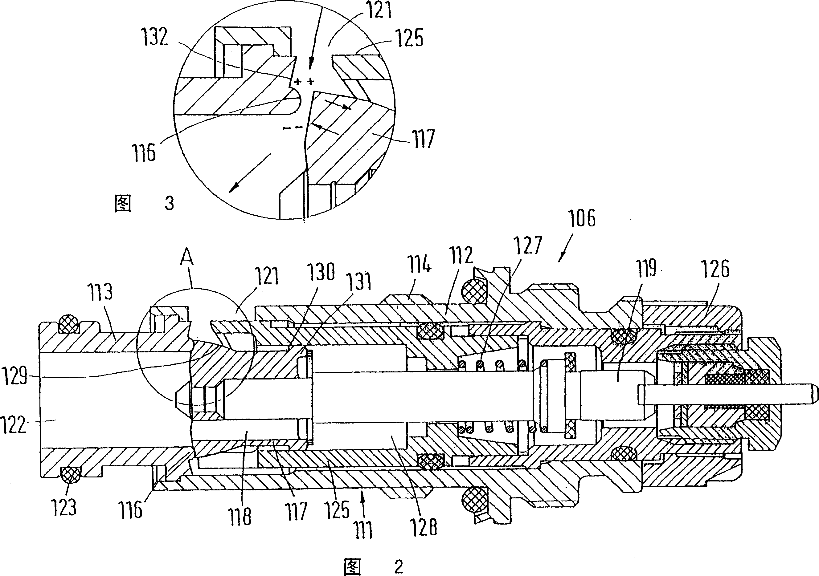
[0022] The plug-in valve 6 is fixed on the end face of the first section 2 by a threaded sleeve 10 . It has a housing 11 with a screw-in 12 and a shoulder 13 . The screw-in part 12 is connected to the threaded sleeve 10 via a thread 14 and to the shoulder 13 via a thread 15 . The shoulder has a valve seat 16 which cooperates with a closure 17 which has a pressure relief channel 18 and is actuated by a thermostat 20 via a valve rod 19 . Other features resulting in pressure relie...


PUM


Abstract

An insert valve for a sectional radiator (1), comprising a housing (6) extending through a first section (2), a valve seat (16) cooperating with an externally operated sealing member (17), an inlet duct extending from the periphery of the housing (21), and an outlet duct leading to a second section (3). The sealing element (17) is relieved from pressure. The inlet duct (21) is disposed in a lateral position close to the sealing element (17). The outlet duct (22) is joined to the valve seat (16) on the opposite side to said sealing element (17), thereby providing an insert valve which has a simple design and can therefore be produced at low cost.

Description

technical field [0001] The invention relates to an insert valve for a segmented radiator, having a housing penetrating into a first segment and having a valve seat cooperating with an externally operable closure and a valve seat extending from the periphery of the housing. an inflow channel to the second section and an outflow channel to the second section. Background technique [0002] Such an insertion valve is known from DE4330149A1. Since it is connected to the first section, it controls the flow of heat carrier from the first section to the second section and thus controls all other sections of the radiator. The housing has an inflow channel consisting of a radial bore and an axial bore leading to the valve seat. The outflow channel is formed by a through-opening, which connects the space next to the closure part with the end face of the housing facing the second section. Therefore, the casing has a very complicated structure and is expensive to produce. Contents o...

Claims


Application Information

Patent Timeline
Patent Type & Authority Patents(China)
IPC IPC(8): F16K31/68F24D19/10F24H9/12
CPCF24D19/0012
Inventor F·加姆
Owner DANFOSS AS
Why Eureka
Try Eureka