Adjusting device for a turbocharger, and turbocharger

A technology of exhaust gas turbine and supercharger, which is applied in the direction of mechanical equipment, gas turbine devices, shafts and bearings, etc. It can solve problems such as looseness, stress material fatigue, etc., and achieve the effect of improving service life

Active Publication Date: 2018-08-31
IHI CHARGING SYST INT
View PDF8 Cites 0 Cited by
  • Summary
  • Abstract
  • Description
  • Claims
  • Application Information

AI Technical Summary

Problems solved by technology

Continuous changes in component expansion due to repeated tempe...

Method used


Image

  • Adjusting device for a turbocharger, and turbocharger
  • Adjusting device for a turbocharger, and turbocharger
  • Adjusting device for a turbocharger, and turbocharger

Examples


Embodiment Construction

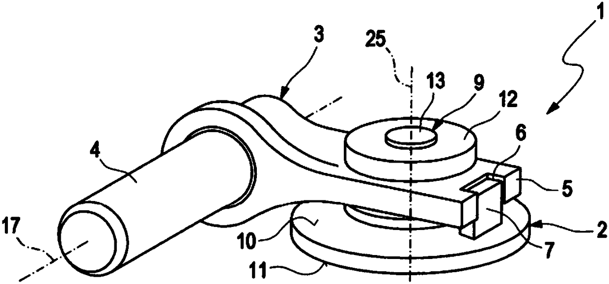
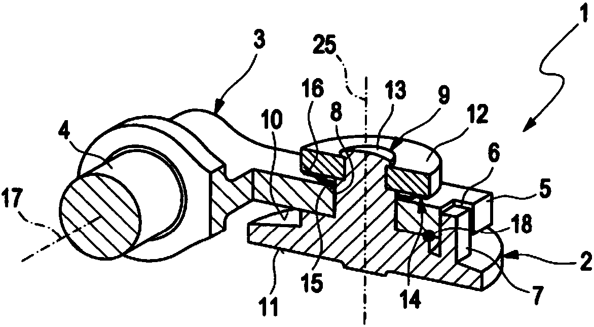
[0024] A control device 1 of an exhaust gas turbocharger according to the prior art (not shown in detail) is designed as shown in FIG. 1 . The exhaust gas turbocharger has a flowable exhaust gas guide section, not shown in detail, through which a fluid, usually exhaust gas, flows through during operation of the exhaust gas turbocharger. The exhaust gases are generally combustion products of an internal combustion engine, not shown in detail. Control devices of this type are known by the term wastegate device.

[0025] The exhaust gas turbocharger is assigned an air guide section (not shown in detail) through which flow can flow, and a bearing section (not shown in detail) positioned between the exhaust gas guide section and the air guide section, wherein the bearing section A rotor arrangement, not shown in detail, is rotatably accommodated therein. The rotor arrangement has a compressor wheel (not shown in detail) and a turbine wheel (not shown in detail), which are connect...


PUM


Abstract

The invention relates to a control device for an exhaust turbocharger, comprising an exhaust gas conducting section through which fluid can flow and which includes a bypass duct for bypassing a turbine wheel that is rotatably arranged in the exhaust gas conducting section, and comprising an adjusting arm (3) for accommodating a valve element (2) provided for opening or blocking a flow cross-section of the bypass duct; the adjusting arm (3) is movably accommodated in the exhaust gas conducting section; furthermore, a flexible element (14) is provided at least for securing the valve element (2)in place on the adjusting arm (3). According to the invention, the flexible element (14) is designed so as to be radially slidable in order to reduce adjustment forces.

Description

technical field [0001] The invention relates to a regulating device for an exhaust gas turbocharger of the type specified in the preamble of claim 1 . Furthermore, the invention relates to an exhaust gas turbocharger of the type specified in the preamble of claim 8 . Background technique [0002] From the published document DE 10 2012 101 322 A1 a control device for an exhaust gas turbocharger with a turbine is known, wherein the turbine has an exhaust gas guide section through which flow can flow and a bypass channel for the The purpose is to bypass the exhaust gas flow around the turbine arranged in the exhaust gas conduction section. The adjustment device comprises a valve element for closing the bypass channel, and an adjustment arm which accommodates the valve element. The adjusting arm is mounted rotatably in the exhaust gas guide section. The positioning of the valve element on the adjusting arm is ensured by means of a spring element in order to avoid noise during...

Claims


Application Information

Patent Timeline
IPC IPC(8): F02B37/18F01D17/10F01D17/12F01D11/00
CPCF05D2240/40F16C2360/24F16C17/02F16C27/02F02B37/186Y02T10/12F02C6/12F05D2220/40
Inventor 拉尔夫·沙韦尔延斯·茨韦丁格
Owner IHI CHARGING SYST INT
Why Eureka
Try Eureka